Caterpillar 320C Excavator Supplement for 3066 Engine Page 85
Supplement
85
Excavator Supplement for 3066 Engine
Disassembly and Assembly Section
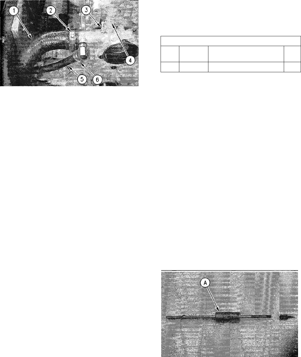
17. Install alternator mounting bracket (8).
18. Install bolt (7) that secures alternator mounting
bracket (8) to the engine.
Illustration 337
19. Install heater hose (5) to the front housing and
tighten hose clamp (6).
20. Install hose (4) to the front housing. Tighten
hose clamp (3).
21. Install
radiator hose (1). Tighten hose clamp (2).
End By:
a. Install the fuel injection pump. Refer to
Disassembly and Assembly, "Fuel Injection
Pump - Install".
b. Install the crankshaft pulley. Refer to Disassembly
and Assembly, "Crankshaft Pulley - Remove and
Install".
c. Install the water pump. Refer to Disassembly and
Assembly, "Water Pump - Install".
d. Install the alternator. Refer to Disassembly and
Assembly, "Alternator - Install".
e. Install the radiator. Refer to Disassembly and
Assembly, "Radiator - Install".
Crankshaft Front Seal -
Remove
SMCS Code: 1160-011
Removal Procedure
Table 15
Required Tools
Tool
(A)
Part
Number
1U-7600
Part Description
Slide Hammer Puller
Qty
1
Start By:
a. Remove the crankshaft pulley. Refer to
Disassembly and Assembly, "Crankshaft Pulley
- Remove and Install".
NOTICE
Keep all parts clean from contaminants.
Contaminants may cause rapid wear and shortened
component life.
NOTICE
Care must be taken to ensure that fluids are contained
during performance of inspection, maintenance, test-
ing, adjusting and repair of the product. Be prepared to
collect the fluid with suitable containers before open-
ing any compartment or disassembling any compo-
nent containing fluids.
Refer to Special Publication, NENG2500, "Caterpillar
Tools and Shop Products Guide" for tools and supplies
suitable to collect and contain fluids on Caterpillar
products.
Dispose of all fluids according to local regulations and
mandates.
Illustration 338
Photo of Tooling (A)
g00713226
Contents Summary of Caterpillar 320C Excavator Supplement for 3066 Engine
- Page 1CATERPILLAR RENR3813-01 December 2000 Supplemental Information 3 2 0 C Excavator Supplement for 3 0 6 6 Engine APA1-Up (Machine) ANB1-Up (Machine) BCB1-Up (Machine) BDB1-Up (Machine) BGB1-Up (Machine) AMC1-Up (Machine) BBC1 -Up (Machine) BDC1-Up (Machine) CC01-Up (Machine) ALF1-Up (Machine) BEF1-Up
- Page 2Important Safety Information Most accidents that involve product operation, maintenance and repair are caused by failure to observe basic safety rules or precautions. An accident can often be avoided by recognizing potentially hazardous situations before an accident occurs. A person must be alert to
- Page 33 Excavator Supplement for 3066 Engine Table of Contents Table of Contents Engine and Main Hydraulic Pump - Install 109 Flywheel and Ring Gear - Remove and Install ..119 Crankshaft Rear Seal - Remove 121 Crankshaft Rear Seal - Install 122 Disassembly and Assembly Section Hydraulic System Pressure -
- Page 44 Excavator Supplement for 3066 Engine Disassembly and Assembly Section Disassembly and Assembly NOTICE Section Care must be taken to ensure that fluids are contained during performance of inspection, maintenance, test- ing, adjusting and repair of the product. Be prepared to collect the fluid with
- Page 55 Excavator Supplement for 3066 Engine Disassembly and Assembly Section Note: If the desired hydraulic circuit that requires Perform the following Steps in order to release the service requires the activation of a switch for hydraulic pressure from multiple hydraulic circuits operation, activate the
- Page 66 Excavator Supplement for 3066 Engine Disassembly and Assembly Section 12. Repeat Steps 4 through 11 for each additional hydraulic circuit that requires service. 13. After releasing the hydraulic pressure in each of the desired hydraulic circuits, place the hydraulic activation control lever in the
- Page 77 Excavator Supplement for 3066 Engine Disassembly and Assembly Section 3. Install the spacer, the washer, and bolt (8) to the alternator. 4. Install the washer and bolt (7) to the alternator. Illustration 6 Rear view of the alternator 8i Support alternator (1). Remove bolt (9), the washer, and the
- Page 88 Excavator Supplement for 3066 Engine Disassembly and Assembly Section io-1341994 2. R e m o v e nut (2) a n d the washer. D i s c o n n e c t battery cables (3). Electric Starting Motor - Remove and Install SMCS Code: 1453-010 Removal Procedure Start By: a. Deactivate the electrical system. Refer
- Page 99 Excavator Supplement for 3066 Engine Disassembly and Assembly Section End By: a. Install the hood. Refer to Disassembly and Assembly, "Hood - Remove and Install" in this manual. b. Activate the electrical system. Refer to Operation and Maintenance Manual, "Battery Disconnect Switch" in order to ac
- Page 1010 Excavator Supplement for 3066 Engine Disassembly and Assembly Section 7. Remove two bolts (10) and the washers in order to remove two clamps (11) that secure the governor linkage to the chassis. Note: Some models may only have one clamp (11). Illustration 21 5. Remove two nuts (6) that secure gov
- Page 1111 Excavator Supplement for 3066 Engine Disassembly and Assembly Section Illustration 26 Illustration 28 3. Install two clamps (11) that secure the governor 6. Install governor linkage (7) to the fuel injection linkage to the chassis. pump. Fasten governor linkage (7) with washers and two nuts (6).
- Page 1212 Excavator Supplement for 3066 Engine Disassembly and Assembly Section 11. Check the governor actuator. Reference: Refer to Systems Operation/Testing and Adjusting, "Governor Actuator - Calibrate" for further information. Fuel Priming Pump - Remove and Install SMCS Code: 1258-010 Removal Procedure
- Page 1313 Excavator Supplement for 3066 Engine Disassembly and Assembly Section Note: O-rings, gaskets, and seals should always be replaced. 1. Clean the surfaces that make contact with gasket (3). Install new gasket (3). 2. Install fuel priming pump (4). 3. Install the washers and two bolts (2). Illustrat
- Page 1414 Excavator Supplement for 3066 Engine Disassembly and Assembly Section Installation Procedure 4. Close hood (1). NOTICE Care must be taken to ensure that fluids are contained during performance of inspection, maintenance, test- Water Separator - Remove and ing, adjusting and repair of the product.
- Page 1515 Excavator Supplement for 3066 Engine Disassembly and Assembly Section 5. Remove two bolts (2) and the washers. Remove water separator (4). Installation Procedure NOTICE Care must be taken to ensure that fluids are contained during performance of inspection, maintenance, test- ing, adjusting and r
- Page 1616 Excavator Supplement for 3066 Engine Disassembly and Assembly Section Illustration 44 Illustration 46 4. Close the left side access doors. 4. Remove O-ring seal (3) from the dipstick tube. Installation Procedure Engine Oil Level Gauge (Dipstick) - Remove and Install SMCSCode: 1326-011; 1326-012 R
- Page 1717 Excavator Supplement for 3066 Engine Disassembly and Assembly Section i01342042 Engine Oil Filter and Oil Filter Base - Remove and Install SMCS Code: 1306-010; 1308-010 Removal Procedure Table 2 • Required Tools Part Tool Number Part Description Qty (A) 2P-8250 Strap Wrench Assembly 1 Illustratio
- Page 1818 Excavator Supplement for 3066 Engine Disassembly and Assembly Section 1. Install gasket (9) on the engine. Illustration 51 Illustration 54 7. Remove eight bolts (8) and the washers from engine oil filter base (1). 2. Install engine oil filter base (1) on the engine. 8. Remove engine oil filter ba
- Page 1919 Excavator Supplement for 3066 Engine Disassembly and Assembly Section 7. Install the washers and three bolts (3) in order to install bracket assembly (2) and base assembly (1). 8. Close drain valve (4). 9. If filter (5) was removed, install filter (5). 10. Check the engine oil level. Refer to Ope
- Page 2020 Excavator Supplement for 3066 Engine Disassembly and Assembly Section Illustration 59 Illustration 62 a. Remove two O-rings (6) from the bracket e. Remove relief valve (9). assembly (2). b. Remove cap (5) to the oil sampling valve. Illustration 63 f. Remove seal washer (12) from relief valve (9).
- Page 2121 Excavator Supplement for 3066 Engine Disassembly and Assembly Section i01353311 Engine Oil Filter Base - Assemble SMCS Code: 1306-016; 1306 Assembly Procedure Note: The filter base comes in two sections: The first section is the base assembly (3) and the second section is the bracket assembly (2)
- Page 2222 Excavator Supplement for 3066 Engine Disassembly and Assembly Section Illustration 70 Illustration 73 e. Install two plugs (14) to the oil filter base (3). d. Install seal washer (12) to relief valve (9). 2. Use the following procedure to assemble the e. Install relief valve (9). bracket assembly
- Page 2323 Excavator Supplement for 3066 Engine Disassembly and Assembly Section End By: a. Install the engine oil filter and filter bases. Refer to Disassembly and Assembly, "Engine Oil Filter and Oil Filter Base - Install" in this manual. i01342037 Engine Oil Cooler - Remove and Install SMCS Code: 1378-01
- Page 2424 Excavator Supplement for 3066 Engine Disassembly and Assembly Section Illustration 79 Illustration 81 1. Remove bolts (1) and the washers that secure 1. Install a new gasket (3) to the cover for the the oil cooler (2) to the engine cylinder block. engine oil cooler. Ensure that all mating surface
- Page 2525 Excavator Supplement for 3066 Engine Disassembly and Assembly Section Note: A hydraulic oil sample should be obtained before any maintenance is performed in order Hydraulic Oil Cooler - Remove to establish the system contaminant level. Refer to Fluid Analysis Laboratory Guide, SEBF3116, SMCS Code
- Page 2626 Excavator Supplement for 3066 Engine Disassembly and Assembly Section 6. Open two side doors (6). Illustration 88 Illustration 85 10. Remove three screws (12). Remove two screens 7. Loosen hose clamp (8). Disconnect hose (7) (13). from the air cleaner housing. Illustration 89 Illustration 86 11.
- Page 2727 Excavator Supplement for 3066 Engine Disassembly and Assembly Section Illustration 90 Illustration 93 14. Remove four bolts (20) and the washers. 17. Remove four bolts (24) and the washers from oil Disconnect tube (19) from oil cooler (18). cooler (18). The weight of the oil cooler is 16 kg (35 l
- Page 2828 Excavator Supplement for 3066 Engine Disassembly and Assembly Section Illustration 94 Illustration 97 Note: Use two persons to install the oil cooler. 5. Connect tube (19) to oil cooler (18). Install the washers and four bolts (20). 1. Carefully install oil cooler (18). The weight of the oil cool
- Page 2929 Excavator Supplement for 3066 Engine Disassembly and Assembly Section 8. Place two screens (12) in position. Install three screws (13). Illustration 103 Illustration 100 12. Close side doors (6). 9. Place the support and air filter (9) in position on the machine. Install the washers and bolts (11
- Page 3030 Excavator Supplement for 3066 Engine Disassembly and Assembly Section 19. If the S.O.S sample exceeds ISO 18/15, flush the hydraulic system. Reference: Refer to Contamination Control Guidelines, SEBF8436, "Hydraulic System Flushing Procedure for 320C Hydraulic Excavators" for further information.
- Page 3131 Excavator Supplement for 3066 Engine Disassembly and Assembly Section Illustration 110 Illustration 113 8. Loosen hose clamp (13) and disconnect air inlet hose (12): 9. Remove four bolts (14) and washers that hold the air cleaner housing into position. 10. Remove air cleaner housing (8). Illustra
- Page 3232 Excavator Supplement for 3066 Engine Disassembly and Assembly Section Installation Procedure 5. Connect air inlet hose (12) to air cleaner housing (8) and tighten hose clamp (13). Illustration 116 Illustration 119 1. Install hood assembly (16) to the air cleaner housing (8). 6. Connect electrical
- Page 3333 Excavator Supplement for 3066 Engine Disassembly and Assembly Section Illustration 122 Illustration 125 8. Install valve (7) to cover (5). 11. Close the access door (3) on the front left side of the machine. Illustration 123 Illustration 126 9. Install O-ring seal (6) to cover (5). 12. Install co
- Page 3434 Excavator Supplement for 3066 Engine Disassembly and Assembly Section 3. Remove bolts (3) from the bracket for the fuel NOTICE priming pump. Keep all parts clean from contaminants. Contaminants may cause rapid wear and shortened component life. Illustration 130 4. Remove bolts (4) and the washers
- Page 3535 Excavator Supplement for 3066 Engine Disassembly and Assembly Section Air Inlet Manifold - Install SMCS Code: 1058-012-AI Installation Procedure NOTICE Keep all parts clean from contaminants. Contaminants may cause rapid wear and shortened component life. Illustration 135 5. Install bolts (3) in
- Page 3636 Excavator Supplement for 3066 Engine Disassembly and Assembly Section b. Install the fuel injection lines. Refer to Disassembly and Assembly, "Fuel Injection Lines - Remove and Install". c. Install the fuel filter base. Refer to Disassembly and Assembly, "Fuel Filter Base - Remove and Install". i
- Page 3737 Excavator Supplement for 3066 Engine Disassembly and Assembly Section Illustration 142 900721911 Illustration 144 8. Remove gasket (9) from the air inlet heater. 1. Install wire mesh filter (10). illustration 143 Illustration 145 900721911 9. Remove wire mesh filter (10). 2. Install gasket (9) on
- Page 3838 Excavator Supplement for 3066 Engine Disassembly and Assembly Section 8. Connect electrical wire (3) to the air inlet heater. Install nut (2). 9. Install rubber boot (1) on the electrical connector. 10. Close the engine hood. i01368404 Muffler - Remove and Install SMCSCode: 1062-010 Removal Proce
- Page 3939 Excavator Supplement for 3066 Engine Disassembly and Assembly Section Installation Procedure Illustration 155 3. Loosen clamp (3). Slide clamp (3) onto pipe (4). Remove pipe (4), clamp (3), and the gasket that 1. Place muffler (7) in position on the brackets in the is between pipe (4) and the tur
- Page 4040 Excavator Supplement for 3066 Engine Disassembly and Assembly Section b. Remove the V-Belts from the alternator. Refer to Disassembly and Assembly, "V-Belts - Remove and Install" in this manual. Illustration 158 4. Apply 4C-5599 Anti-Seize Compound to the threads of nuts (2). Install nuts (2). Il
- Page 4141 Excavator Supplement for 3066 Engine Disassembly and Assembly Section Illustration 162 Illustration 165 g0072i959 The radiator is removed for photographic purposes. 5. Remove gasket (6). 5. Install bolt (1) in the alternator. Installation Procedure End By: a. Install the V-Belts on the alternator
- Page 4242 Excavator Supplement for 3066 Engine Disassembly and Assembly Section 2. Loosen hose clamp (3). Disconnect air line (4). Illustration 170 Illustration 167 7. Remove nut (11) and the bolt in order to remove 3. Remove bolts (5) and the washers. Remove heat the clamp. shield (6). 8. Remove turbochar
- Page 4343 Excavator Supplement for 3066 Engine Disassembly and Assembly Section Turbocharger - Install SMCSCode: 1052-012 Installation Procedure Installation Procedure of the Turbocharger Housing Illustration 173 2. Loosen exhaust clamp (16). Illustration 176 1. Install the gasket (not shown) on the exhaus
- Page 4444 Excavator Supplement for 3066 Engine Disassembly and Assembly Section yi-i*v*» Illustration 181 2. Install turbocharger cartridge (12). 3. Install the bolt and nut (11) in order to install the clamp. Illustration 179 7. Install inner nuts (15). Install outer nuts (14). Illustration 182 Installati
- Page 4545 Excavator Supplement for 3066 Engine Disassembly and Assembly Section Water Temperature Regulator - Remove and Install SMCSCode: 1355-010 Removal Procedure WARNING At operating temperature, the engine coolant is hot and under pressure. Illustration 184 Steam can cause personal injury. 7. Install
- Page 4646 Excavator Supplement for 3066 Engine Disassembly and Assembly Section 2. Drain the engine coolant to a level below the 6. Remove gasket (6). water temperature regulator. Drain the engine coolant into a suitable container for storage or 7. Use the following procedure to test the water disposal. te
- Page 4747 Excavator Supplement for 3066 Engine Disassembly and Assembly Section 6. Fill the radiator with coolant to the correct level. Refer to Operation and Maintenance Manual for further information. •ustration 190 gOO/10743 2. Install water temperature regulator (8). Illustration 193 Note: O-rings, gas
- Page 4848 Excavator Supplement for 3066 Engine Disassembly and Assembly Section I P ^ ^ W " ' " ill I-'"! 1 • 'l'i"> ^ I :••..!.• * y|Hmii#wiiHNinnpml3 i^MpHpe' jllll IIBiHIBIIIlil 1 illiilB^ Illustration 194 1. Open hood (1). Lock the engine hood in the OPEN Position. Illustration 196 Illustration 195 2.
- Page 4949 Excavator Supplement for 3066 Engine Disassembly and Assembly Section Blustration 198 Illustration 200 5. Disconnect the fuel injection lines (7) from the 10. Loosen the acorn nuts (11), which secure the fuel injection nozzles (6). fuel return line to the fuel injection nozzles. Note: Cap all ope
- Page 5050 Excavator Supplement for 3066 Engine Disassembly and Assembly Section Illustration 202 3. Connect fitting (10) of the fuel return line to the fuel injection pump. 4. Install the washer and bolt (8) through the clamp in order to secure the fuel return line to the inlet manifold. 5. Place the fuel
- Page 5151 Excavator Supplement for 3066 Engine Disassembly and Assembly Section NOTICE Keep all parts clean from contaminants. Contaminants may cause rapid wear and shortened component life. NOTICE Care must be taken to ensure that fluids are contained during performance of inspection, maintenance, test- i
- Page 5252 Excavator Supplement for 3066 Engine Disassembly and Assembly Section 4. Remove three bolts (5) and the washers in order to remove access panel (4). Illustration 212 Bottom view of the engine Illustration 210 10. Remove oil line (9) from the nipple (not shown). 5. Disconnect hose assembly (7) fro
- Page 5353 Excavator Supplement for 3066 Engine Disassembly and Assembly Section 13. Remove bolts (17) and washers that secure the cover (18) to the engine front housing. •ustration215 The radiator is removed for photographic purposes. 14. Remove gasket (19). Illustration 217 15. Mark the gears for later in
- Page 5454 Excavator Supplement for 3066 Engine Disassembly and Assembly Section 3. Install the fuel injection pump. i01342315 4. Install the washers and four bolts (23) that secure Fuel Injection Pump - Install the fuel injection pump to the front housing. SMCSCode: 1251-012 Installation Procedure NOTICE K
- Page 5555 Excavator Supplement for 3066 Engine Disassembly and Assembly Section lustration 223 Illustration 226 The radiator is removed for photographic purposes. 12. Connect the hose. Tighten hose clamp (11). 8. Install the washers and bolts (17) that secure cover (18) to the engine front housing. 13. Con
- Page 5656 Excavator Supplement for 3066 Engine Disassembly and Assembly Section Start By: a. Remove the fuel injection lines. Refer to Disassembly and Assembly, "Fuel Injection Lines - Remove and Install". NOTICE Keep all parts clean from contaminants. Contaminants may cause rapid wear and shortened compon
- Page 5757 Excavator Supplement for 3066 Engine Disassembly and Assembly Section SL Carefully remove fuel injection nozzle (4). Note: Align the centerline of Tooling (A) with the extended centerline of fuel injection nozzle (4). This . procedure will help prevent distortion of the fuel injection nozzle whic
- Page 5858 Excavator Supplement for 3066 Engine Disassembly and Assembly Section 6. Remove three acorn nuts (5) and washers in order to remove valve mechanism cover (6). 7. Remove valve mechanism cover (6). Illustration 235 1. Open the engine hood. Illustration 238 8. Loosen hose clamp (13) and remove breat
- Page 5959 Excavator Supplement for 3066 Engine Disassembly and Assembly Section tion 240 Illustration 242 1. Install gaskets (14) onto valve mechanism covers 5. Install valve mechanism cover (6). Install the (6) and (10). washers and three acorn nuts (5). Note: O-rings, gaskets, and seals should always be
- Page 6060 Excavator Supplement for 3066 Engine Disassembly and Assembly Section 11. Close the engine hood. 2. Loosen six short bolts (4) and the washers on the rocker shaft brackets. 3. Loosen six long bolts (2) for the rocker shaft Rocker Shaft and Push Rod - bracket. Remove 4. Remove six long bolts (2) f
- Page 6161 Excavator Supplement for 3066 Engine Disassembly and Assembly section i01342327 Rocker Shaft and Push Rod - Install SMCSCode: 1102-012; 1208-012 Installation Procedure NOTICE Keep all parts clean from contaminants. Contaminants may cause rapid wear and shortened component life. Illustration 250 3
- Page 6262 Excavator Supplement for 3066 Engine Disassembly and Assembly Section b. Remove the exhaust manifold. Refer to Disassembly and Assembly, "Exhaust Manifold - Remove and Install". c. Remove the rocker shaft and pushrods. Refer to Disassembly and Assembly, "Rocker Shaft and Pushrod - Remove". d. Rem
- Page 6363 Excavator Supplement for 3066 Engine Disassembly and Assembly Section lustration 254 Illustration 255 Typical example Typical example Note: When the gasket is removed from the cylinder 1. Clean the surfaces of the cylinder head and the block, be careful not to damage the mounting face cylinder bl
- Page 6464 Excavator Supplement for 3066 Engine Disassembly and Assembly Section e. Install the engine hood. Refer to Disassembly and Assembly, "Hood - Remove and Install". Radiator - Remove SMCSCode: 1353-011 Removal Procedure Table 7 Required Tools Illustration 257 Part Torque sequence for the cylinder he
- Page 6565 Excavator Supplement for 3066 Engine Disassembly and Assembly Section 4. Loosen hose clamp (4). Disconnect lower NOTICE radiator hose (5). Care must be taken to ensure that fluids are contained during performance of inspection, maintenance, test- ing, adjusting and repair of the product. Be prepa
- Page 6666 Excavator Supplement for 3066 Engine Disassembly and Assembly Section Illustration 264 Illustration 267 9. Remove wing bolts (10). Remove screens (11) 12. Remove bolts (14) and the washers that secure from the front of the hydraulic oil cooler. the radiator to the support. Note: The bottom half o
- Page 6767 Excavator Supplement for 3066 Engine Disassembly and Assembly Section Remove bolts (17) and the washers. Remove Fan shroud (16). Radiator - Install SMCS Code: 1353-012 Installation Procedure • Required Tools Part Illustration 272 Tool Number Part Description Qty (A) 138-7573 Link Bracket 2 3. Fas
- Page 6868 Excavator Supplement for 3066 Engine Disassembly and Assembly Section (6 lllustration 275 Illustration 278 This is a view of the bottom of the radiator. 7. Install screens (11) on the front of the hydraulic oil cooler. Install wing bolts (10). 11. Install the washers and bolts (6) in the bottom h
- Page 6969 Excavator Supplement for 3066 Engine Disassembly and Assembly Section NOTICE Care must be taken to ensure that fluids are contained during performance of inspection, maintenance, test- ing, adjusting and repair of the product. Be prepared to collect the fluid with suitable containers before open-
- Page 7070 Excavator Supplement for 3066 Engine Disassembly and Assembly Section Fan - Remove and Install SMCSCode: 1356-011; 1356-012 Removal Procedure WARNING At operating temperature, the engine coolant is hot and under pressure. Steam can cause personal injury. Illustration 283 The radiator is removed f
- Page 7171 Excavator Supplement for 3066 Engine Disassembly and Assembly Section 2. Drain the engine coolant to a level below the 5. Remove bolts (7) and the washers. Remove fan upper radiator hose into a suitable container for (8) and spacer (6). storage or disposal. Installation Procedure NOTICE Care must
- Page 7272 Excavator Supplement for 3066 Engine Disassembly and Assembly Section Water Pump - Remove SMCS Code: 1361-011 Removal Procedure Start By: a. Remove the fan. Refer to Disassembly and Assembly, "Fan- Remove and Install" in this manual. b. Remove the V-belts. Refer to Disassembly and Illustration 29
- Page 7373 Excavator Supplement for 3066 Engine Disassembly and Assembly Section Start By: a. Remove the water pump. Refer to Disassembly and Assembly, "Water Pump - Remove" in this manual. WARNING Always wear protective gloves when handling parts that have been heated. Note: If the water pump is heated up
- Page 7474 Excavator Supplement for 3066 Engine Disassembly and Assembly Section 2. Use Tooling (B) to remove retaining ring (2) from 7. Check seal (12) for wear and damage. Use the water pump. Tooling (C) in order to remove the seal from the water pump housing, if necessary. Note: Replace the seal if any s
- Page 7575 Excavator Supplement for 3066 Engine Disassembly and Assembly Section • bearing (8) Note: Check two bearings (8) and (10) for correct Water Pump - Install rotation. SMCSCode: 1361-012 3. Install a new O-ring seal (5). Installation Procedure NOTICE Care must be taken to ensure that fluids are cont
- Page 7676 Excavator Supplement for 3066 Engine Disassembly and Assembly Section WARNING Personal injury can result from hot coolant, steam and alkali. At operating temperature, engine coolant is hot and under pressure. The radiator and all lines to heaters or the engine contain hot coolant or steam. Any co
- Page 7777 Excavator Supplement for 3066 Engine Disassembly and Assembly Section i01342375 Water Outlet Manifold - Install SMCSCode: 1362-012 Installation Procedure NOTICE Keep all parts clean from contaminants. Contaminants may cause rapid wear and shortened component life. •ustration 304 Note: Put identif
- Page 7878 Excavator Supplement for 3066 Engine Disassembly and Assembly Section 6. Install two wires in the original location. Fasten the two wires with two screws (1). Tighten the screws to a torque of .98 ± .245 N.m (8.674 ± 2.1684 lb in). 7. Install wire tie-wraps (3). End By: a. Install the water tempe
- Page 7979 Excavator Supplement for 3066 Engine Disassembly and Assembly Section Illustration 313 900712742 4. Remove the woodruff key (5) from the crankshaft. 2. Install woodruff key (5) to the crankshaft. Tap the woodruff key at one end with a hammer in order to dislodge the key. Illustration 314 •ustrati
- Page 8080 Excavator Supplement for 3066 Engine Disassembly and Assembly Section End By: NOTICE a. Install the V-belts. Refer to Disassembly and Care must be taken to ensure that fluids are contained Assembly, "V-Belts - Remove and Install". during performance of inspection, maintenance, test- ing, adjustin
- Page 8181 Excavator Supplement for 3066 Engine Disassembly and Assembly Section 5. Remove alternator mounting bracket (8). Illustration 321 lustration 318 10. Remove bolts (15) and the washers that mount 6. Disconnect electrical connector (9). Remove wire the front housing to oil pan (14). (10) and the con
- Page 8282 Excavator Supplement for 3066 Engine Disassembly and Assembly Section Illustration 323 Illustration 325 13. Remove two bolts (19) and the washers that mount the front housing (16) to the front plate and the cylinder block. 14. Use two technicians to remove the front housing from the cylinder bloc
- Page 8383 Excavator Supplement for 3066 Engine Disassembly and Assembly Section NOTICE keep all parts clean from contaminants. Contaminants may cause rapid wear and shortened component life. Illustration 329 4. Before installation of the front housing, check the gasket (22) for the oil pan for damage. Repl
- Page 8484 Excavator Supplement for 3066 Engine Disassembly and Assembly Section 10. Install one clip, the nuts, the washers, and two bolts (18) to the front housing (16). Illustration 334 Illustration 331 13. Support the refrigerant compressor and mounting bracket (12). 11. Install two bolts (19) in order
- Page 8585 Excavator Supplement for 3066 Engine Disassembly and Assembly Section 17. Install alternator mounting bracket (8). 18. Install bolt (7) that secures alternator mounting Crankshaft Front Seal - bracket (8) to the engine. Remove SMCS Code: 1160-011 Removal Procedure Table 15 Required Tools Part Too
- Page 8686 Excavator Supplement for 3066 Engine Disassembly and Assembly Section Illustration 339 Illustration 340 gOO/14156 Exploded view of Tooling (A), the front seal, and the nut (5). 1. Drill three evenly spaced 3 mm (0.12 inch) holes in crankshaft front seal (1). 1. Clean the faces of all the mating p
- Page 8787 Excavator Supplement for 3066 Engine Disassembly and Assembly Section i01342288 Oil Pan - Remove and Install SMCS Code: 1302-010 Removal Procedure Note: Before you begin the following procedure, swing the upper frame so that the upper frame is parallel with the undercarriage. NOTICE Care must be
- Page 8888 Excavator Supplement for 3066 Engine Disassembly and Assembly Section Illustration 346 5. Remove bolts (7) and the washers from the Note: Mark the location of clip (13) for the drain hinge. tube. 6. Remove bolts (5) and the washers in order to 9. Remove bolts (11) and the washers. remove access p
- Page 8989 Excavator Supplement for 3066 Engine Disassembly and Assembly Section Illustration 352 g00709926 Illustration 355 g00709936 14. Remove bolts (16) in order to remove plate (17). 18. Remove O-ring seal (21) from the oil level switch. Installation Procedure fci -jy-y-J ••». :,.•••:,:-• •• •••s*ssu—.
- Page 9090 Excavator Supplement for 3066 Engine Disassembly and Assembly Section Illustration 358 Illustration 361 4. Install plate (18) and the oil level switch in the 7. Install drain valve (14) in the oil pan. oil pan. 8. Thoroughly clean the mating surfaces of the oil pan and the engine block. 9. Instal
- Page 9191 Excavator Supplement for 3066 Engine Disassembly and Assembly Section Illustration 363 Illustration 366 12. Connect electrical connector (10) for the engine 16. Install access panel (3) that is located under the oil level switch. main pump. Install the washers and bolts (1). 17. Install access pa
- Page 9292 Excavator Supplement for 3066 Engine Disassembly and Assembly Section WARNING Personal injury can result from contact with refrig- erant. Contact with refrigerant can cause frost bite. Keep face and hands away to help prevent injury. Protective goggles must always be worn when re- frigerant lines
- Page 9393 Excavator Supplement for 3066 Engine Disassembly and Assembly Section 5. Remove four bolts (4) and the washers. Remove refrigerant compressor (5). Installation Procedure Illustration 372 3. Remove the tape from the refrigerant compressor. Connect tube assemblies (2). Install the washers and bolts
- Page 9494 Excavator Supplement for 3066 Engine Disassembly and Assembly Section WARNING Personal injury can result from contact with refrig- Refrigerant Condenser erant. Remove and Install Contact with refrigerant can cause frost bite. Keep SMCSCode: 1805-010 face and hands away to help prevent injury. S/N
- Page 9595 Excavator Supplement for 3066 Engine Disassembly and Assembly Section Removal Procedure WARNING Personal injury can result from contact with refrig- erant. Contact with refrigerant can cause frost bite. Keep face and hands away to help prevent injury. Protective goggles must always be worn when r
- Page 9696 Excavator Supplement for 3066 Engine Disassembly and Assembly Section 7. Remove four bolts (7) and washers from the two mounting brackets (6). Installation Procedure WARNING Personal injury can result from contact with refrig- erant. Contact with refrigerant can cause frost bite. Keep face and ha
- Page 9797 Excavator Supplement for 3066 Engine Disassembly and Assembly Section Reference: Refer to Testing and Adjusting, "Refrigerant System - Charge" for the correct procedure. 9. Check the entire air conditioning system for leaks. Note: Use a 4C-2964 Electronic Leak Detector to check for leaks. Hood -
- Page 9898 Excavator Supplement for 3066 Engine Disassembly and Assembly Section 7. Carefully remove hood (1) from the machine. The weight of the hood is 34 kg (75 lb). Installation Procedure Illustration 382 3. Remove cotter pin (2) and the washer that holds support (3) in place. Illustration 385 g00709389
- Page 9999 Excavator Supplement for 3066 Engine Disassembly and Assembly Section Install the washers and two bolts (4) to the left c. Deactivate the electrical system. Refer to side hinge. Operation and Maintenance Manual, "Battery Disconnect Switch" in order to deactivate the electrical system. Table 17 Re
- Page 100100 Excavator Supplement for 3066 Engine Disassembly and Assembly Section WARNING WARNING At operating temperature, the hydraulic oil is hot Personal injury can result from contact with refrig- and under pressure. Hot oils can cause burns. erant. To prevent possible personal injury, release the Cont
- Page 101101 Excavator Supplement for 3066 Engine Disassembly and Assembly Section 6. Remove four bolts (3) and the washers. 7. Remove cover (4). •;*z 'tit Illustration 390 3. Remove eight bolts and the washers in order to remove two access covers (1) that are under the Illustration 393 main hydraulic pump.
- Page 102102 Excavator Supplement for 3066 Engine Disassembly and Assembly Section Illustration 395 Illustration 397 Left side view of the main pump 16. Disconnect two hose assemblies (9) from the 13. Disconnect electrical connector (6). pilot pump. 14. Disconnect three hose assemblies (7) from the main pump
- Page 103103 Excavator Supplement for 3066 Engine Disassembly and Assembly Section 21. Remove the bolts (14a), the washers and the split flanges. 22. Disconnect two hose assemblies (14) from the main pump. Illustration 402 27. Remove four bolts (20) that hold suction line (19) in position. Illustration 400 R
- Page 104104 Excavator Supplement for 3066 Engine Disassembly and Assembly Section NOTICE Care must be taken to ensure that fluids are contained during performance of inspection, maintenance, test- ing, adjusting and repair of the product. Be prepared to collect the fluid with suitable containers before open
- Page 105105 Excavator Supplement for 3066 Engine Disassembly and Assembly Section Illustration 407 Illustration 410 Top view of alternator 39. Remove bolts (31) and the washers from the hinge. 42. Remove the nut and the washer behind rubber boot (35). Disconnect the wire behind the rubber 40. Remove bolts (
- Page 106106 Excavator Supplement for 3066 Engine Disassembly and Assembly Section 54. Remove bolt (48), the washer, and the harness clip. Illustration 412 50. Disconnect electrical connection (43) from the Illustration 415 refrigerant compressor. 55. Remove the bolts and the washers that fasten the harness
- Page 107107 Excavator Supplement for 3066 Engine Disassembly and Assembly Section Illustration 417 Illustration 420 58. Remove nut (52) and the washer. Disconnect 61. Loosen hose clamp (59). battery cables (53). 62. Disconnect upper radiator hose (58) at the water temperature regulator. Illustration 418 59.
- Page 108108 Excavator Supplement for 3066 Engine Disassembly and Assembly Section 71. Disconnect electrical connector (69) from the flywheel. Illustration 422 68. Remove bolt (65) in order to disconnect the Illustration 425 ground strap. 72. Disconnect electrical connector (70) from the air inlet heater. 73
- Page 109109 Excavator Supplement for 3066 Engine Disassembly and Assembly Section Illustration 427 Illustration 430 76. Loosen hose clamp (74) in order to disconnect 80. Remove bolts (81) and the washers. Remove the lower radiator hose. two rear engine mounts (82). 77. Loosen hose clamp (75) in order to dis
- Page 110110 Excavator Supplement for 3066 Engine Disassembly and Assembly Section 4. Make sure that rubber mounts (79) are in the correct position in the frame. 5. Lower the engine onto the frame. 6. Install rubber mounts (78) and washer (77) on the engine mounts. 7. Install the washers and bolts (76). Inst
- Page 111111 Excavator Supplement for 3066 Engine Disassembly and Assembly Section 15. Tighten nuts (68) in order to connect the governor control cables. 16. Connect governor control cable (66). Connect governor control cable (67). Illustration 436 11. Install the washer and bolt (71) in the clip for the wir
- Page 112112 Excavator Supplement for 3066 Engine Disassembly and Assembly Section 22. Tighten two hose clamps (60). Illustration 444 Illustration 441 27. Connect battery cables (53). Install the washer 23. Connect upper radiator hose (58) to the water and nut (52). temperature regulator. 24. Tighten hose cl
- Page 113113 Excavator Supplement for 3066 Engine Disassembly and Assembly Section Illustration 447 g00722093 Illustration 450 31. Install the harness clip, the washer, and bolt (48). 36. Connect electrical connection (41). 32. Connect electrical connections (46) and (47). 37. Install two screws (42) in orde
- Page 114114 Excavator Supplement for 3066 Engine Disassembly and Assembly Section 40. Install the washer and bolt (38) in order to connect two ground wires to alternator (34). 41. Connect the wire that is located behind the rubber boot. Install the washer and the nut that is located behind rubber boot (35):
- Page 115115 Excavator Supplement for 3066 Engine Disassembly and Assembly Section 50. Install the washers and four bolts (23) in support 55. Install the nut, the washers, and bolt (18) in (21). order to install the clamp on the main pump. 51. Install upper shield (22). 52. Install the washers and six bolts
- Page 116116 Excavator Supplement for 3066 Engine Disassembly and Assembly Section Illustration 463 Illustration 465 60. Connect two hose assemblies (14) to the main 66. Connect two hose assemblies (9) to the pilot pump. pump. 61. Install the split flanges, the washers and bolts (14a). 62. Connect two electr
- Page 117117 Excavator Supplement for 3066 Engine Disassembly and Assembly Section 68. Connect three hose assemblies (7) to the main 74. Close access door (2) on the right side of the pump, machine. 69. Connect electrical connector (6). n Illustration 471 Illustration 468 900689094 75. Install two access cov
- Page 118118 Excavator Supplement for 3066 Engine Disassembly and Assembly Section WARNING NOTICE Personal injury can result from contact with refrig- When the main hydraulic pump has been serviced or erant. the hydraulic oil has been replaced, the air in the hy- draulic system must be purged. Do not start t
- Page 119119 Excavator Supplement for 3066 Engine Disassembly and Assembly Section 101301806 4. Use two M16 X 2 forcing screws (3) in order to remove flywheel (1). Flywheel and Ring Gear - Remove and Install 5. Remove flywheel (1). The weight of the flywheel is 41 kg (90 lb). SMCS Code: 1156-011; 1156-012; 1
- Page 120120 Excavator Supplement for 3066 Engine Disassembly and Assembly Section 7. Remove four spring pins (6). a. Heat the ring gear to 150 °C (302 °F) in an oven. Installation Procedure b. Position ring gear (5) so the part number is facing toward the crankshaft. Table 20 c. Press ring gear (5) onto fly
- Page 121121 Excavator Supplement for 3066 Engine Disassembly and Assembly Section 1. Remove two bolts (1) and washers from the flywheel housing. Crankshaft Rear Seal - Remove SMCS Code: 1161-011 Removal Procedure Table 21 Required Tools Part Tool Number Part Description Qty (A) 1U-7600 Slide Hammer Puller 1
- Page 122122 Excavator Supplement for 3066 Engine Disassembly and Assembly Section 101342162 Crankshaft Rear Seal - Install SMCSCode: 1161-012 Installation Procedure Table 22 Required Tools Part Tool Number Part Description Qty 9U-6169 Installer 1 Illustration 482 9U-6171 Locator 1 (A) 9U-6172 Bolts 2 5P-824
- Page 123123 Excavator Supplement for 3066 Engine Disassembly and Assembly Section 6. Push the wear sleeve that is complete with a seal onto the crankshaft until 9U-6169 Installer (2) bottoms out. 7. Remove Tooling (A) and check crankshaft rear seal (1) for correct installation. End By: a. Install the flywhe
- Page 124124 Excavator Supplement for 3066 Engine Index Section Index A Engine Oil Filter Base - Assemble 21 Assembly Procedure 21 Air Cleaner- Remove and Install .. 30 Engine Oil Filter Base - Disassemble 19 Installation Procedure 32 Disassembly Procedure 19 Removal Procedure 30 Engine Oil Level Gauge (Dips
- Page 125125 Excavator Supplement for 3066 Engine Index Section Hydraulic Oil Cooler - Install 27 W Installation Procedure 27 Hydraulic Oil Cooler - Remove 25 Water Outlet Manifold - Install 77 Removal Procedure 25 Installation Procedure 77 Hydraulic System Pressure - Release 4 Water Outlet Manifold - Remove