C27 and C32 Generator Set Engines Specifications Page 28
Specifications
28 RENR7167-02
Specifications Section
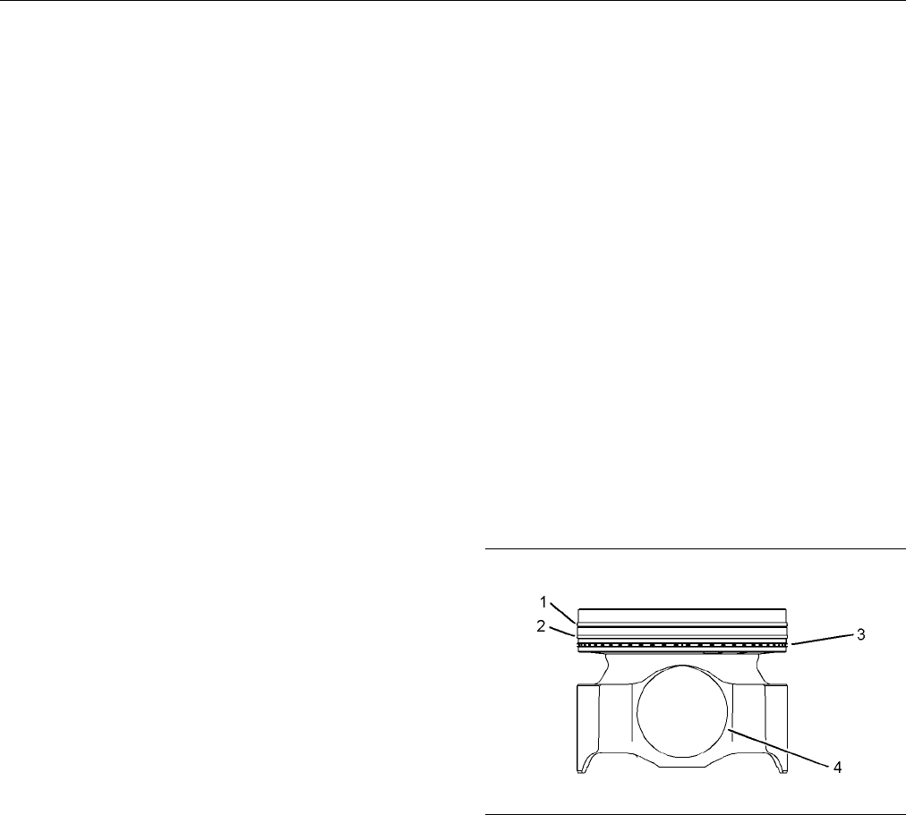
Install the piston ring with “UP-1” mark toward the
top of the pisto
n.
There is a clearance between the ends of the piston
ring. When the
piston ring is installed in a cylinder
liner with a bore of 137.16 mm (5.400 inch), the
clearance is the following value. ...... 0.40 ± 0.10 mm
(0.02 ± 0.004
inch)
There is an increase in the clearance between
the ends of th
e piston rings for each 0.030 mm
(0.0012 inch) increase in the cylinder liner bore.
Increase .................................. 0.08 mm (0.003 inch)
Intermediate Piston Ring
(2) Intermediate piston ring
Install the p
istonringwith“UP-2”marktowardthe
top of the piston.
There is a cl
earance between the ends of the piston
ring. When the piston ring is installed in a cylinder
liner with a bore of 137.16 mm (5.400 inch), the
clearance i
s the following value. .... 0.77 ± 0.125 mm
(0.0303 ± 0.0049 inch)
There is an i
ncrease in the clearance between
the ends of the piston rings for each 0.030 mm
(0.0012 inch) increase in the cylinder liner bore.
Increase .................................. 0
.08 mm (0.003 inch)
Oil Contro
lRing
(3) Oil C ontrol Ring
The spring ends of the oil control ring should be
assembled 180 degrees from the ring end gap.
Width of groove in new piston for oil control
ring ................................................... 3 .02 ± 0.01 mm
(0.119 ± 0
.001 inch)
Thickness of new oil control ring ...... 2.98 ± 0.01 mm
(0.117 ± 0
.001 inch)
There is a clearance between the ends of the piston
ring. Whe
n the piston ring is installed in a cylinder
liner with a bore of 137.16 mm (5.400 inch), the
clearance is the following value. ...... 0.55 ± 0.15 mm
(0.028 ±
0.006 inch)
There is an increase in the clearance between
the ends
of the piston rings for each 0.030 mm
(0.0012 inch) increase in the cylinder liner bore.
Increase .................................. 0.08 mm (0.003 inch)
Piston Pin Bore
(4) Piston pin bore
Diameter of the bore in the bearing that is installed into
the piston s kirt for the piston pin .... 59.40 ± 0.04 mm
(2.339 ± 0.002 i
nch)
Diameter of the new piston pin .. 59.975 ± 0.005 mm
(2.3612 ± 0.00
02 inch)
i02417176
Piston and Rings
SMCS Code: 1214; 1215
Part No.: 213-4835
S/N: SXC1-Up
Part No.: 213-4835
S/N: MED1-Up
Part No.: 213-4835
S/N: WDR1-Up
g01091802
Illustration 53
Note: Refer to Guideline for Reusable Parts for
information on the pistons, the piston pins, and the
retaining rings.
The 1U-6431 Piston Ring Groove Gauge Gp is
used for measuring the ring grooves in keystone
style pistons. Refer to the Special Instruction that is
supplied with the Piston Ring Groove Gauge.
The 5P-3519 Piston Ring Groove Gauge Gp is
available for checking the ring grooves with straight
sides. Refer to the Guideline for Reusable Parts for
instructions on the Piston Ring Groove Gauge.
Top Piston Ring
(1) Top piston ring
Contents Summary of C27 and C32 Generator Set Engines Specifications
- Page 1RENR7167-02 July 2007 Specifications C27 and C32 Generator Set Engines DWB1-Up (Generator Set) SXC1-Up (Generator Set) MED1-Up (Power Module) WDR1-Up (Generator Set)�
- Page 2i01658146 Important Safety Information Most accidents that involve product operation, maintenance and repair are caused by failure to observe basic safety rules or precautions. An accident can often be avoided by recognizing potentially hazardous situations before an accident occurs. A person must b
- Page 3RENR7167-02 3 Table of Contents Table of Contents Index Section Index ..................................................................... 43 Specifications Section Engine Design ....................................................... 4 Engine Design ................................................
- Page 44 RENR7167-02 Specifications Section Specifications Section Note: Number one cylinder is the front cylinder on the left side of the cylinder block. Number two cylinder is the front cylinder on the right side of the i02810716 cylinder block. Engine Design Firing order ............ 1, 10, 9, 6, 5, 12,
- Page 5RENR7167-02 5 Specifications Section Note: The front of the engine is opposite of the Run the pump at 840 rpm with the inlet open to the flywheel end of the engine. The left side of the engine atmosphere for 10 seconds. Block the inlet. The and the right side of the engine is viewed from the pump mu
- Page 66 RENR7167-02 Specifications Section i02792816 1. Tighten the bolt for the clamp to 55 ± 10 N·m (41 ± 7 lb ft). Electronic Unit Injector Mechanism 2. Loosen the bolt for the clamp until the bolt is finger tight. SMCS Code: 1290 3. Tighten the bolt for the clamp again to 55 ± 10 N·m Part No.: 235-140
- Page 7RENR7167-02 7 Specifications Section i02815204 Valve Mechanism SMCS Code: 1102 Part No.: 260-9631 g01401981 Illustration 7 View A-A Typical example (3) Bearing joint (B) Bore g01246863 Illustration 8 New parts ............................ 40.065 ± 0.015 mm (1) Rocker arm (1.5774 ± 0.0006 inch) (4) C
- Page 88 RENR7167-02 Specifications Section i02794903 Valve Mechanism SMCS Code: 1102 Part No.: 223-6398 S/N: DWB1-Up Part No.: 223-6398 S/N: SXC1-Up g01404154 Illustration 9 Left side of engine g01404155 g01246863 Illustration 10 Illustration 12 Right side of engine (1) Rocker arm (4) Camshaft (6) Valve b
- Page 9RENR7167-02 9 Specifications Section i02794979 Cylinder Head Valves SMCS Code: 1105 Part No.: 223-6431, 284-8892 g01400357 Illustration 13 Left side of engine g01400358 Illustration 14 Right side of engine (7) Torque for bolts ........ 109 ± 15 N·m (80 ± 11 lb ft) g01395835 Illustration 15 Note: App
- Page 1010 RENR7167-02 Specifications Section (A) Height to the step that is in the valve Bore in cylinder head for valve seat insert guide ............... 35.0 ± 0.5 mm (1.38 ± 0.02 inch) (exhaust valve) .................... 42.774 ± 0.025 mm (1.6840 ± 0.0010 inch) (B) New valve stem diameter ...... 9.441
- Page 11RENR7167-02 11 Specifications Section i02697086 Cylinder Head SMCS Code: 1100 Part No.: 223-6397, 279-7453, 284-8895 S/N: DWB1-Up Part No.: 223-6397, 279-7453, 284-8895 S/N: SXC1-Up Part No.: 284-8895 S/N: MED1-Up Part No.: 223-6397, 279-7453, 284-8895 S/N: WDR1-Up g01144556 Illustration 17 Bolt tig
- Page 1212 RENR7167-02 Specifications Section g01353140 Illustration 20 Orientation of bearing joint (C) .......................... 20 ± 3 degrees below horizontal g01353135 Illustration 18 (3) Oil gallery (4) Camshaft bearing (5) Typical location for cup plug (6) Oil holes g01353461 Illustration 21 The dep
- Page 13RENR7167-02 13 Specifications Section i02383782 i02797500 Turbocharger Exhaust Manifold SMCS Code: 1052 SMCS Code: 1059 Part No.: 261-0501, 267-4742, 294-3666 Part No.: 261-0500 S/N: DWB1-Up S/N: DWB1-Up Part No.: 246-4411, 261-0501, 297-1024 Part No.: 252-0768, 261-0500 S/N: SXC1-Up S/N: SXC1-Up Pa
- Page 1414 RENR7167-02 Specifications Section Note: The end of the camshaft that is marked “F” must be placed at the front of the engine. Lubricate the camshaft bearings, the journals, and the lobes with a 50/50 mixture of 8T-2998 Lubricant and clean engine oil. (A) Diameter of camshaft journal .. 84.85 ± 0
- Page 15RENR7167-02 15 Specifications Section i02798297 3. Subtract the base circle measurement in Step 2 from the camshaft lobe height in Step 1. The Camshaft difference is the actual lobe lift. SMCS Code: 1210 (B) Specified camshaft lobe lift Part No.: 246-4409, 260-9308 Exhaust lobe ......... 8.51520 mm
- Page 1616 RENR7167-02 Specifications Section i02798318 Engine Oil Filter Base SMCS Code: 1306 Part No.: 264-1492 g01402272 Illustration 31 Section A-A (3) 4N-8150 Spring Length under test force ... 55.24 mm (2.175 inch) g01188271 Test force .......... 75.619 ± 5.800 N (17.0 ± 1.3 lb) Illustration 30 Free l
- Page 17RENR7167-02 17 Specifications Section g01207495 Illustration 33 (1) Diameter of new drive shaft .. 22.217 ± 0.005 mm (0.8747 ± 0.0002 inch) (2) Diameter of new idler shaft .. 22.217 ± 0.005 mm (0.8747 ± 0.0002 inch) (3) 2S-2760 Spring Length under test force .. 117.14 mm (4.612 inch) Test force ....
- Page 1818 RENR7167-02 Specifications Section g01402275 Illustration 34 Right side view of engine (1) Apply a light coat of glycerin to the O-ring seals and the bores for the O-ring seals.�
- Page 19RENR7167-02 19 Specifications Section i02799191 Note: Do not install the lip type seal (1) by hand. Use the installation tool and a press to install the lip type Water Temperature Regulator seal. Make sure that the primary lip is toward the water pump drive gear. Press the lip type seal until SMCS C
- Page 2020 RENR7167-02 Specifications Section i02798357 (A) Thickness of the spacer plates ..................................... 8.585 ± 0.025 mm Cylinder Block (0.3380 ± 0.0010 inch) SMCS Code: 1201 (B) Thickness of plate gasket that is between cylinder block and spacer plate ........... 0.208 ± 0.025 mm P
- Page 21RENR7167-02 21 Specifications Section g01398970 Illustration 39 Marks for tightening main bearings 1. Apply clean engine oil on the threads of the main bearing cap bolts (8). Loosely install the main bearing cap bolts (8). g01398978 Illustration 40 2. Apply clean engine oil on the threads of the sid
- Page 2222 RENR7167-02 Specifications Section (A) Bore in new cylinder liner .. 137.185 ± 0.025 mm (A) Bore in new cylinder liner .. 145.000 ± 0.025 mm (5.4010 ± 0.0010 inch) (5.7086 ± 0.0010 inch) (B) Dimensions for flange (1) (B) Dimensions for flange (1) Thickness of flange on cylinder Thickness of flang
- Page 23RENR7167-02 23 Specifications Section g01399550 Illustration 43 Typical example (3) Main journal (4) Rod journal Note: Thrust plates (1) are used on the center main Note: The seal and the sleeve can not be used if the bearing only. seal and the sleeve have been separated. (A) Thickness of new thrust
- Page 2424 RENR7167-02 Specifications Section i02664969 i02801053 Vibration Damper and Pulley Vibration Damper and Pulley SMCS Code: 1205 SMCS Code: 1205 Part No.: 256-6003 Part No.: 267-2104 S/N: DWB1-Up Part No.: 267-2104 S/N: SXC1-Up Part No.: 267-2104 S/N: WDR1-Up g01188235 Illustration 45 (1) Damper (4
- Page 25RENR7167-02 25 Specifications Section i02664967 Connecting Rod Bearing Journals Vibration Damper and Pulley Table 1 Diameter of Crankshaft Journal (Bearing SMCS Code: 1205 Surface) For Connecting Rod Part No.: 301-6972 Original Size 97.028 ± 0.020 mm S/N: SXC1-Up (3.8200 ± 0.0008 inch) Part No.: 301
- Page 2626 RENR7167-02 Specifications Section i02801090 6. Tighten bolts (1) and (3) again to 70 ± 4 N·m (50 ± 3 lb ft). Connecting Rod 7. Tighten bolts (1) and (3) by an additional angle SMCS Code: 1218 (A) of 60 ± 5 degrees. Part No.: 232-3232 S/N: DWB1-Up Part No.: 215-1955, 232-3232 S/N: SXC1-Up Part No
- Page 27RENR7167-02 27 Specifications Section g01399634 g01401199 Illustration 50 Illustration 51 (7) Oil jet tube assembly Note: The bearing joint must be located within area (E) along the horizontal centerline of the piston pin (8) Torque for the special bolt of oil jet tube bore. assembly ...............
- Page 2828 RENR7167-02 Specifications Section Install the piston ring with “UP-1” mark toward the Piston Pin Bore top of the piston. (4) Piston pin bore There is a clearance between the ends of the piston ring. When the piston ring is installed in a cylinder Diameter of the bore in the bearing that is insta
- Page 29RENR7167-02 29 Specifications Section Install the piston ring with “UP-1” mark toward the Diameter of the bore in the bearing that is installed into top of the piston. the piston skirt for the piston pin .... 59.40 ± 0.04 mm (2.339 ± 0.002 inch) There is a clearance between the ends of the piston ri
- Page 3030 RENR7167-02 Specifications Section g01399843 Illustration 55 Note: The rear face of the front housing assembly (3) and the front face of the cylinder block must be free of oil, fuel, water, dirt and any other contaminants during assembly. The gasket for the front housing assembly must also be fre
- Page 31RENR7167-02 31 Specifications Section i02801118 Housing (Rear) SMCS Code: 1157 Part No.: 233-2462 g01399863 g01399864 Illustration 57 Illustration 58 Left side view of engine View A-A (3) Cylinder block Note: The rear face of the cylinder block and the front face of the rear housing (1) must be free
- Page 3232 RENR7167-02 Specifications Section i02801133 Gear Group (Front) SMCS Code: 1206 Part No.: 235-0993 g01399869 g01399881 Illustration 59 Illustration 60 Rear view (1) Damper group (3) Gear assembly (5) Crankshaft gear Use the following procedure to tighten the bolts for (6) Gear the rear housing: 1
- Page 33RENR7167-02 33 Specifications Section (7) Torque for the bolt ........ 55 ± 10 N·m (41 ± 7 lb ft) i02801439 Gear Group (Rear) SMCS Code: 1204; 1206 Part No.: 224-1213 g01399922 Illustration 62 Section A-A (8) Lubricate the drive idler shaft with clean engine oil. Note: Install the thrust plate with
- Page 3434 RENR7167-02 Specifications Section g01400123 g01400787 Illustration 64 Illustration 65 Tightening sequence Section A-A Note: Tighten the bolts for the camshaft gear in the (12) Lubricate the O-ring seals lightly with clean sequence 1, 4, 2, 5, 3, 6, 1, 4. Refer to Illustration 64. engine oil. (4)
- Page 35RENR7167-02 35 Specifications Section Note: Tighten the twelve bolts in a circular pattern. 2. In the numerical sequence that is shown in The circular pattern can be in a clockwise direction Illustration 67, torque bolt (3) through bolt (10) to or in a counterclockwise direction. 135 ± 20 N·m (100 ±
- Page 3636 RENR7167-02 Specifications Section i02801662 3. In the numerical sequence that is shown in Illustration 69, torque bolt (11) through bolt (34) to Flywheel Housing 47 ± 9 N·m (35 ± 7 lb ft). Bolts (11) through bolts (34) are 3/8-16 X 2 1/2 inches. SMCS Code: 1157 (35) The seal driver must not cont
- Page 37RENR7167-02 37 Specifications Section i02801674 Engine Support (Rear) SMCS Code: 1154 Part No.: 234-5913 S/N: DWB1-Up Part No.: 234-5913 S/N: SXC1-Up Part No.: 234-5913 S/N: WDR1-Up g01302592 Illustration 72 Rear view Use the following procedure to tighten the studs and bolts: 1. Tighten stud (9) th
- Page 3838 RENR7167-02 Specifications Section i02385671 i02806500 Engine Support (Rear) Alternator and Regulator SMCS Code: 1154 SMCS Code: 1405; 1410 Part No.: 236-8766 Part No.: 5N-5692 S/N: DWB1-Up S/N: DWB1-Up Part No.: 236-8766 Part No.: 5N-5692 S/N: SXC1-Up S/N: SXC1-Up Part No.: 236-8766 Part No.: 5N
- Page 39RENR7167-02 39 Specifications Section Output voltage ............................................. 28 ± 1 V i02806498 Note: Tighten the bolt (1) before tightening the Fuel Temperature Sensor mounting bolt. SMCS Code: 1922 (1) Torque for the bolt .... 88.4 ± 6.8 N·m (65 ± 5 lb ft) Part No.: 264-4297
- Page 4040 RENR7167-02 Specifications Section i02665532 (1) Sensor assembly Engine Oil Pressure Sensor Tighten sensor assembly to the following torque. ............................... 10 ± 2 N·m (90 ± 18 lb in) SMCS Code: 1924 Operating temperature ........................ −40 to 125 °C Part No.: 274-6719 (
- Page 41RENR7167-02 41 Specifications Section i02666631 Operating temperature ........................ −40 to 125 °C (−40 to 257 °F) Atmospheric Pressure Sensor Maximum operating pressure (absolute SMCS Code: 1923 pressure) ......................................... 116 kPa (17 psi) Part No.: 194-6724 i02786
- Page 4242 RENR7167-02 Specifications Section Operating temperature ........................ −40 to 125 °C (1) Tighten the sensor to the following (−40 to 257 °F) torque. ........................ 10 ± 2 N·m (90 ± 18 lb in) Maximum operating pressure (absolute Operating voltage ..............................
- Page 43RENR7167-02 43 Index Section Index A I Alternator and Regulator ....................................... 38 Important Safety Information ................................... 2 Atmospheric Pressure Sensor............................... 41 Inlet Air Temperature Sensor................................. 42
- Page 44©2007 Caterpillar All Rights Reserved Printed in U.S.A.