CAT D3K, D4K and D5K Track-Type Tractors Operation and Maintenance Manual Page 65
Operation and Maintenance Manual
SEBU8213-04 65
Operation Section
Machine Operation
i03739620
Operation Information
SMCS Code: 7000
To prevent inj
ury, make sure that no people are
workingonthemachineornearthemachine.To
prevent injury, keep the machine under control at all
times.
Reduce machine speed when you maneuver in tight
quarters or
when you are going over a hill.
Select the necessary travel speed before you start
downhill.
When you go downhill, use the same speed that
wouldbeus
ed to go uphill.
Use the decele rator/brake pedal on a downgrade in
order to m
aintain a safe operating mode. Use the
following controls in order to slow down the travel
speed of the machine: decelerator/brake pedal and
buttons f
or speed control.
When the load will be pushing the machine, push
the spee
d selector to LOW speed before you start
downhill.
1. Adjust t
he operator's seat.
2. Fasten the seat belt.
3. Raise all lowered attachments in order to negotiate
any obstacles.
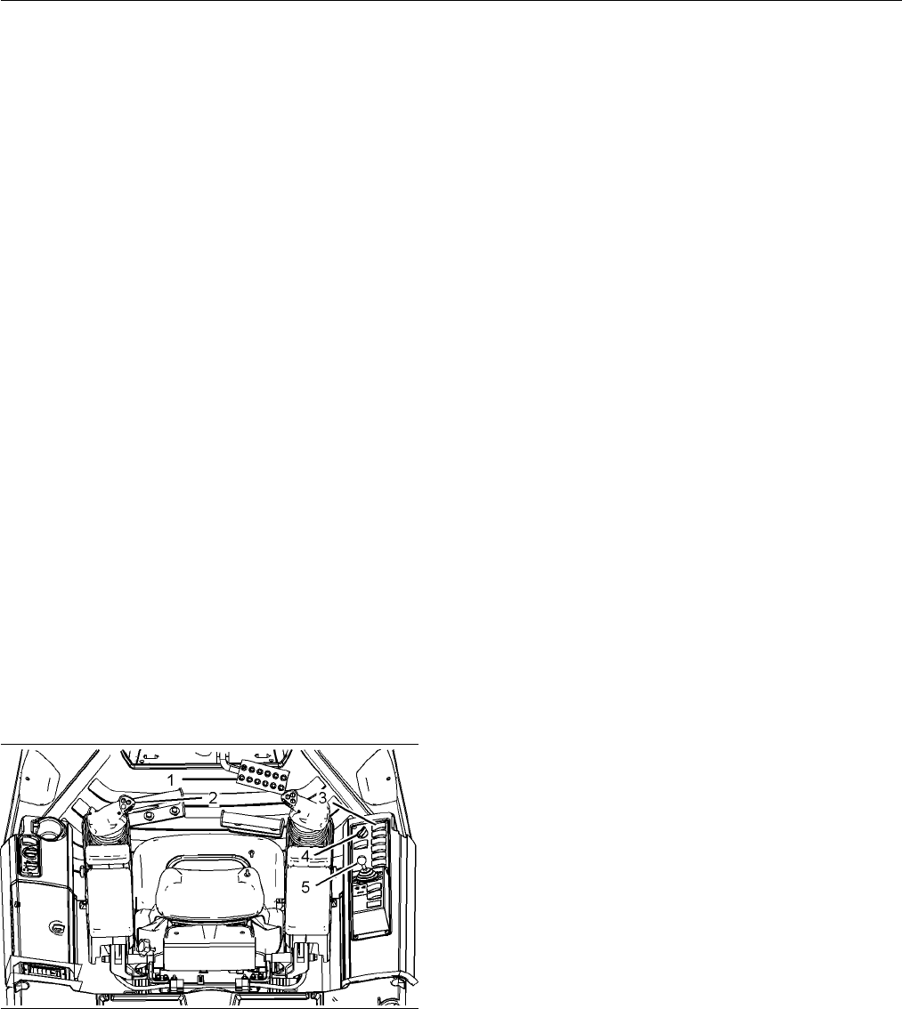
g01258916
Illustration 91
(1) Dece lerator/brake pedal
(2) Steering and transmission control (lever)
(3) P arking br ake switch
(4) Engine throttle control (knob)
(5) Winch control lever or r ipper control lever (if equipped)
4. Push down on pedal (1) in order to prevent the
machine from moving.
5. Move switch (3)
toward the operator to the
DISENGAGED position.
6. Turn knob (4) i
n order to set the desired engine
speed.
Note: The d ec
elerator/brake pedal can be depressed
in order to temporarily reduce travel speed.
7. Move lever (
2) for the desired direction.
8. Release pedal (1).
9. Roll the thumb wheel for the ground speed control
in order to set the desired ground speed. The
wheel for t
he ground speed control is located on
lever (2).
10. Drive the m
achine forward for best visibility and
for best control.
Hydrostatic Drive Operating
Principl
e
This machine has a hydrostatic drive system which
transfe
rs power from the engine to the tracks. The
hydrostatic drive system eliminates the conventional
type of transmission. The hydrostatic drive system
does not
use a bevel gear and a driveline. The
hydrostatic drive system also eliminates the steering
clutch and brake arrangement.
In the simplest form, a hydrostatic drive system is a
system which contains the following components: a
hydra
ulic pump with a control system, a hydraulic
motor, and high pressure lines that carry oil between
the components. The pump converts mechanical
power
to hydraulic power in the form of oil flow and
oil pressure.
To m e e
t requirements, the machine must be able to
move forward and rearward. The machine must also
be able to turn. The pumps are designed to deliver
vary
ing flows of oil to either the forward side or the
reverse side of the hydraulic motors.
The t
rack can be driven at varying speeds in either a
forward direction or in a reverse direction.
Sin
ce there are two tracks, there are two hydraulic
pumps, two sets of hydraulic lines, and two hydraulic
motors.
Contents Summary of CAT D3K, D4K and D5K Track-Type Tractors Operation and Maintenance Manual
- Page 1SEBU8213-04 October 2009 Operation and Maintenance Manual D3K, D4K and D5K Track-Type Tractors JTD1-Up (Machine) FFF1-Up (Machine) JLF1-Up (Machine) LLL1-Up (Machine) MMM1-Up (Machine) RRR1-Up (Machine) WWW1-Up (Machine) YYY1-Up (Machine) SAFETY.CAT.COM�
- Page 2i03684547 Important Safety Information Most accidents that involve product operation, maintenance and repair are caused by failure to observe basic safety rules or precautions. An accident can often be avoided by recognizing potentially hazardous situations before an accident occurs. A person must b
- Page 3SEBU8213-04 3 Table of Contents Table of Contents Adjustments .......................................................... 71 Parking .................................................................. 73 Foreword ................................................................. 4 Transportation Inform
- Page 44 SEBU8213-04 Foreword Foreword Maintenance The maintenance section is a guide to equipment Literature Information care. The Maintenance Interval Schedule (MIS) lists the items to be maintained at a specific service This manual should be stored in the operator's interval. Items without specific inte
- Page 5SEBU8213-04 5 Foreword It is prohibited for any person engaged in the 3. Check Character (character 9) business of repairing, servicing, selling, leasing, or trading engines or machines to remove, alter, or 4. Machine Indicator Section (MIS) or Product render inoperative any emission related device
- Page 66 SEBU8213-04 Safety Section Safety Messages Safety Section i03193580 Safety Messages SMCS Code: 7000; 7405 g01357030 Illustration 2�
- Page 7SEBU8213-04 7 Safety Section Safety Messages g01357376 Illustration 3 There are several specific safety messages on this machine. The exact location of the hazards and the description of the hazards are reviewed in this section. Please become familiarized with all safety messages. Make sure that all
- Page 88 SEBU8213-04 Safety Section Safety Messages Replace any safety message that is damaged or Seat Belt (2) missing. If a safety message is attached to a part of the machine that is replaced, install a safety message Safety Message (2) is positioned on the left hand on the replacement part. Any Caterpi
- Page 9SEBU8213-04 9 Safety Section Safety Messages Do Not Weld On the ROPS (3) Product Link (4) (if equipped) Safety Message (3) is positioned on the left rear side Safety message (4) is located in the left side of the of the cab post. cab on the front support. g01398698 g01108685 Structural damage, an ov
- Page 1010 SEBU8213-04 Safety Section Safety Messages High Pressure Fuel Lines (6) Hot Fluid Under Pressure (8) Safety Message (6) is located on the left side of the Safety Message (8) is located under the access door engine on the high pressure fuel rail. on the expansion tank filler cap. g01381180 g013709
- Page 11SEBU8213-04 11 Safety Section Safety Messages Improper Connections for Jump Do Not Operate (10) (Winch) Start Cables (9) Safety message (10) is located on the right side of the machine on the vertical wall of the winch frame. Safety Message (9) is located on the right access door outside the operato
- Page 1212 SEBU8213-04 Safety Section Additional Messages Blade and Mast When you use the AccuGrade - Laser System, this safety message is located on the rear of each mast at eye level from the ground. g01282878 g01398723 Illustration 6 There are several specific messages on this machine. To prevent possibl
- Page 13SEBU8213-04 13 Safety Section Additional Messages Air Conditioner (4) (If equipped) This message is located behind the air conditioner compressor on the right side of the engine. g01261266 Illustration 7 Compact Instrument Cluster Film No Step (2) g01399514 Illustration 10 This message is located on
- Page 1414 SEBU8213-04 Safety Section Additional Messages NOTICE When starting from another machine, make sure that the machines do not touch. This could prevent dam- age to engine bearings and electrical circuits. Turn on (close) the battery disconnect switch prior to the boost connection to prevent damage
- Page 15SEBU8213-04 15 Safety Section General Hazard Information i03559343 General Hazard Information SMCS Code: 7000 g01274048 Illustration 13 NOTICE Use only 12 volts to start the engine. Damage to the engine may occur if more than 12 volts are used to g00104545 Illustration 15 start the engine. Attach a
- Page 1616 SEBU8213-04 Safety Section General Hazard Information Keep the equipment free from foreign material. Trapped Pressure Remove debris, oil, tools, and other items from the deck, from walkways, and from steps. Pressure can be trapped in a hydraulic system. Releasing trapped pressure can cause sudden
- Page 17SEBU8213-04 17 Safety Section Crushing Prevention and Cutting Prevention • Tools that are suitable for collecting fluids and • Use exhaust ventilation on permanent machining equipment that is suitable for collecting fluids jobs. • Tools that are suitable for containing fluids and • Wear an approved
- Page 1818 SEBU8213-04 Safety Section Burn Prevention Unless you are instructed otherwise, never attempt Check the coolant level only after the engine has adjustments while the machine is moving or while been stopped. the engine is running. Ensure that the filler cap is cool before removing the Never jump a
- Page 19SEBU8213-04 19 Safety Section Fire Prevention and Explosion Prevention To minimize the risk of fire or explosion, Caterpillar Store fuels and lubricants in properly marked recommends the following actions. containers away from unauthorized personnel. Store oily rags and flammable materials in protec
- Page 2020 SEBU8213-04 Safety Section Fire Prevention and Explosion Prevention Battery and Battery Cables • Discoloration • Cuts on the insulation of the cable • Fouling • Corroded terminals, damaged terminals, and loose terminals Replace damaged battery cable(s) and replace any related parts. Eliminate any
- Page 21SEBU8213-04 21 Safety Section Fire Prevention and Explosion Prevention Attaching electrical wiring to hoses and tubes that Make sure that all clamps, guards, and heat shields contain flammable fluids or combustible fluids should are installed correctly. During machine operation, this be avoided. wil
- Page 2222 SEBU8213-04 Safety Section Fire Extinguisher Location i01834364 • Mount the machine. Fire Extinguisher Location • Dismount the machine. SMCS Code: 7000; 7419 If you are in the operator's station during an electrical storm, stay in the operator's station. If you are on the Make sure that a fire ex
- Page 23SEBU8213-04 23 Safety Section Before Operation Check for the presence of bystanders or maintenance It may not be possible to provide direct visibility on personnel. Ensure that all personnel are clear of the large machines to all areas around the machine. machine. Appropriate job site organization i
- Page 2424 SEBU8213-04 Safety Section Parking Before you move the machine, make sure that no Apply the service brake in order to stop the machine. one will be endangered. The service brake is applied by fully depressing the decel/brake pedal. Move the transmission control to Do not allow riders on the machi
- Page 25SEBU8213-04 25 Safety Section Engine Stopping Direction of travel – Avoid operating the machine i02801029 across the slope. When possible, operate the machine up the slopes and operate the machine Engine Stopping down the slopes. Place the heaviest end of the machine uphill when you are working on a
- Page 2626 SEBU8213-04 Safety Section Sound Information and Vibration Information Hearing protection may be needed when the Information Concerning Whole Body Vibration machine is operated with an open operator station for Level extended periods or in a noisy environment. Hearing protection may be needed whe
- Page 27SEBU8213-04 27 Safety Section Sound Information and Vibration Information Table 1 “ISO Reference Table A - Equivalent vibration levels of whole body vibration emission for earthmoving equipment.” Machine Typical Operating Vibration Levels Scenario Factors Type Activity X axis Y axis Z axis X axis Y
- Page 2828 SEBU8213-04 Safety Section Guards a. Adjust the seat and adjust the controls in order Cab Internal Clearance to achieve good posture. If a machine is equipped with a cab, the position of b. Adjust the mirrors in order to minimize twisted the operator conforms to industry standards. These posture.
- Page 29SEBU8213-04 29 Safety Section Guards Rollover Protective Structure • Rock quarries (ROPS), Falling Object Protective • Forestry products Structure (FOPS) or Tip Over Protection Structure (TOPS) Additional guards may be required for specific applications or work tools. The Operation and The ROPS/FOPS
- Page 3030 SEBU8213-04 Product Information Section General Information Product Information Table 2 Section D3K HYSTAT TRACK-TYPE TRACTOR Operating Weight (LGP)(1) 8093 kg (17842 lb) Operating Weight (XL)(1) 7795 kg (17185 lb) General Information Operating Weight (SLGP)(2) 8190 kg (18055 lb) Length (LGP) (A)
- Page 31SEBU8213-04 31 Product Information Section General Information Table 4 Special attachments and operating instructions are D5K HYSTAT TRACK-TYPE TRACTOR required for Waste Handling applications and other Custom configurations. Operating Weight (LGP)(1) 9683 kg (21347 lb) Operating Weight (XL)(1) 9408
- Page 3232 SEBU8213-04 Product Information Section Identification Information Identification Information The plate for Machine PIN (1) is located to the left of the case on the rear of the machine. The second plate for Machine PIN (1) is located on the left side of i03739400 the radiator guard on the front
- Page 33SEBU8213-04 33 Product Information Section Identification Information g01256144 g01323812 Illustration 30 Illustration 33 The winch serial number is located on the right vertical wall of the winch frame. Do not operate or service the winch unless your first read the Operation and Maintenance Manual
- Page 3434 SEBU8213-04 Product Information Section Identification Information This machine has been certified to the standards that For quick reference, record this information in the are listed on the certification plate. The maximum spaces that are provided below. mass of the machine, which includes the o
- Page 35SEBU8213-04 35 Product Information Section Identification Information For the name, the address and the country of origin for the manufacturer, see the PIN plate. i03722740 Declaration of Conformity SMCS Code: 1000; 7000 Table 5 An EC Declaration of Conformity document was provided with the machine
- Page 3636 SEBU8213-04 Product Information Section Identification Information i03638040 Emissions Certification Film SMCS Code: 1000; 7000; 7405 Note: This information is pertinent in the United States, in Canada and in Europe. Consult your Caterpillar dealer for an Emission Control Warranty Statement. This
- Page 37SEBU8213-04 37 Operation Section Before Operation Operation Section Do not mount a moving machine. Do not dismount a moving machine. Never jump off the machine. Do not try to mount the machine when you carry tools or supplies. Do not try to dismount the machine Before Operation when you are carrying
- Page 3838 SEBU8213-04 Operation Section Before Operation • Operation and Maintenance Manual, “Brakes, Indicators and Gauges - Test” • Operation and Maintenance Manual, “Braking System - Test” • Operation and Maintenance Manual, “Bulldozer Power Angling Tilt Hinge Pins - Lubricate” • Operation and Maintenan
- Page 39SEBU8213-04 39 Operation Section Machine Operation Machine Operation Back Cushion Angle Adjustment (3) – Pull the lever upward. Permit the back i01930019 cushion spring forward or lean backward into the cushion. Release the lever at the desired Alternate Exit position. SMCS Code: 7308; 7310 Fore and
- Page 4040 SEBU8213-04 Operation Section Machine Operation Releasing The Seat Belt Ride Zone Indicator (13) – Use this indicator in order to determine if the suspension is adjusted too high or the adjustment is too low. When the operator sits in the seat, the white bar should be in the green zone of ride zo
- Page 41SEBU8213-04 41 Operation Section Machine Operation Seat Belt Adjustment for Extension of the Seat Belt Retractable Seat Belts Fastening The Seat Belt When using retractable seat belts, do not use seat belt extensions, or personal injury or death can result. The retractor system may or may not lock u
- Page 4242 SEBU8213-04 Operation Section Machine Operation Mirror Adjustment • Stop the engine. Interior Mirror • Adjust the right side rear view mirror in order to view the rear work tool, if equipped. Additionally, provide as much visibility to the rear as possible. Note: You may need to use hand tools in
- Page 43SEBU8213-04 43 Operation Section Machine Operation g01391162 Illustration 48 (1) Adjustable Armrest (11) Bulldozer Control (21) Winch Controls or Ripper Controls (2) Air conditioning and heating Controls (12) Work lights (22) Winch freespool switch (3) Steering and Transmission Control (13) Engine t
- Page 4444 SEBU8213-04 Operation Section Machine Operation Adjustable Armrests (1) Air Conditioning and Heating Control (2) g01269368 Illustration 50 Enclosed ROPS Open ROPS enclosure arrangement has heating only. (2A) Fan control knob (2B) Temperature control knob g01269364 Illustration 49 (2C) Air conditi
- Page 45SEBU8213-04 45 Operation Section Machine Operation Heating and Air Conditioning System Operation The heating and air conditioning system performs five functions: Note: The Open ROPS enclosure arrangement has a heating system only. Heating – Turn knob (2A) to the desired speed (LOW, MEDIUM LOW, MEDIU
- Page 4646 SEBU8213-04 Operation Section Machine Operation REVERSE LEFT (3F) – Move lever (3) to the left in order to turn the machine to the left. The turning HIGH – Roll the wheel (3H) to the right radius for the machine is proportional to the control when a higher speed is desired. lever position. In ord
- Page 47SEBU8213-04 47 Operation Section Machine Operation 3. Roll thumb wheel (3H) to the desired FORWARD The decelerator/brake pedal is configured through speed, while the steering and transmission control ET or the gauge display. The decelerator/brake pedal is in forward. has the two following configurat
- Page 4848 SEBU8213-04 Operation Section Machine Operation CIC Operator Modes Menu The following is displayed on the CIC Operator Modes menu: Mode 0 – Default Mode 1 – Steering Modulation Settings Mode 2 – Implement Modulation Settings Mode 3 – Brake/Decel Pedal Settings See Table 6 for details of the CIC O
- Page 49SEBU8213-04 49 Operation Section Machine Operation Table 6 CIC Menu Operator Modes Maximum Forwards Speed Maximum Reverse Speed Mode 0 Engine Oil Pressure Default Engine Speed System Voltage Service Hour Meter Fine Mode 1 Medium Steering Modulation Settings Coarse Fine Mode 2 Standard Implement Modu
- Page 5050 SEBU8213-04 Operation Section Machine Operation System Voltage Coarse g01329052 g01328936 Illustration 59 Illustration 63 Mode 0 System Voltage LCD Screen Mode 1 - Steering Modulation Settings - Coarse LCD Screen The System Voltage screen indicates the current Mode 2 - Implement Modulation Settin
- Page 51SEBU8213-04 51 Operation Section Machine Operation Mode 3 - Brake/Decel Pedal Settings Enter the cab and close the door until the door latches. Close both doors in order to operate the Brake Pedal Only machine properly. Cab Door Release Lever (9) Machines with cabs are equipped with alternate exits.
- Page 5252 SEBU8213-04 Operation Section Machine Operation Bulldozer Control (11) TILT RIGHT (11F) – Push lever (11) to the right in order to lower the right side of the blade. Lever (11) returns to the HOLD position when the lever is released. Blade Angle (11G) g01257156 Illustration 69 FLOAT (11A) – Push
- Page 53SEBU8213-04 53 Operation Section Machine Operation Low Idle – Rotate knob (13) counterclockwise in order to lower the idle speed. High Idle – Rotate knob (13) clockwise in order to increase the idle speed. Table 7 Throttle Position Engine RPM 1 950 2 1100 g01693534 Illustration 72 3 1175 (12) Work l
- Page 5454 SEBU8213-04 Operation Section Machine Operation Parking Brake Switch (15) Window Wiper and Window Washer (17) (18) (18) (19) (If Equipped) g01695273 Illustration 73 g01391319 Illustration 74 Parking Brake – This switch engages the parking brake. This switch also locks Front Window Wiper Switch (1
- Page 55SEBU8213-04 55 Operation Section Machine Operation Winch Controls or Ripper Controls Note: Do not activate the winch freespool when the machine is moving. (21) Drive Away (23) – Press the winch drive Winch Controls 21, 22, 23 (If Equipped) away switch one time in order to activate this mode. This mo
- Page 5656 SEBU8213-04 Operation Section Machine Operation Use auxiliary switch (24) in order to activate the rear Seat Switch (Tractor Operator) hydraulics when the machine has a winch or a rear attachment. The Operator is Not Present – The seat switch in the operator seat prevents Fire Plow Controls (If E
- Page 57SEBU8213-04 57 Operation Section Machine Operation Fuel Shutoff Control in Cab (If ON – Insert the battery disconnect switch equipped) key, and turn the battery disconnect switch key clockwise in order to activate the electrical system. The switch must be ON before you start the engine. OFF – Turn t
- Page 5858 SEBU8213-04 Operation Section Machine Operation i02513591 The self testing feature verifies that the modules of the monitoring system are properly operating. The Backup Alarm self testing feature verifies that the display module is properly operating. SMCS Code: 7406 The operator must observe the
- Page 59SEBU8213-04 59 Operation Section Machine Operation Run the engine speed at normal rpm. Run the electrical system at a light load. If the light remains on, Hydraulic Oil Filter (3) – This indicator drive the machine to a convenient stop. Investigate is illuminated when the filter is clogged the cause
- Page 6060 SEBU8213-04 Operation Section Machine Operation Gauges Digital Display Window (17) g01211370 g01625713 Illustration 86 Illustration 87 Gauge display (Compact Instrument Cluster) Hydraulic Oil Temperature (13) – The gauge indicates the temperature of the hydraulic oil in the hydraulic oil sump for
- Page 61SEBU8213-04 61 Operation Section Machine Operation Machine Speed (Indicator) i03555467 Speed setting – The indicator displays the speed Product Link setting during machine operation. (If Equipped) Engine Oil Pressure SMCS Code: 7606 Engine oil pressure – The indicator displays the The Product Link P
- Page 6262 SEBU8213-04 Operation Section Machine Operation Operation in a Blast Site Regulatory Compliance If the machine is required to work within 12 m (40 ft) of a blast site, then Product Link PL121SR must be disabled. In order to disable theProduct Link PL121SR install a Product Link Disconnect Switch
- Page 63SEBU8213-04 63 Operation Section Machine Operation g01435306 Illustration 90 Note: A translated extract of the above document is provided below.�
- Page 6464 SEBU8213-04 Operation Section Machine Operation Table 8 DECLARATION OF CONFORMITY We, Quake Global, Inc (Previously Quake Wireless, Inc up to January 2001) of 9765 Clairemont Mesa Blvd, Suite A (Previously 5575 Ruffin Road, Suite 100 up to March 2002) San Diego CA 92124, Usa (Previously 92123) de
- Page 65SEBU8213-04 65 Operation Section Machine Operation i03739620 5. Move switch (3) toward the operator to the DISENGAGED position. Operation Information 6. Turn knob (4) in order to set the desired engine SMCS Code: 7000 speed. To prevent injury, make sure that no people are Note: The decelerator/brake
- Page 6666 SEBU8213-04 Operation Section Machine Operation For the forward modes or the reverse modes, the Operating Principle for the Winch pumps and the motors work in conjunction with each other. The pumps can produce flow to either the forward side of the motors or to the reverse side of the motors. The
- Page 67SEBU8213-04 67 Operation Section Machine Operation The DRIVE AWAY function allows the operator to Using the Winch drive the tractor away from a load while the winch cable is attached to the load. When the winch drive Attaching the Winch Cable away switch is turned on, a spool shifts in the winch dri
- Page 6868 SEBU8213-04 Operation Section Machine Operation i02161716 NOTICE When winding the winch cable on the drum, never at- Prestart Checks tempt to maintain tension by allowing the winch ca- SMCS Code: 7000 ble to slip through the hands. Always use hand-over- hand technique, being very carefull to keep
- Page 69SEBU8213-04 69 Operation Section Engine Starting Engine Starting • The steering and transmission control must be in NEUTRAL. i03322101 • The implement control lever must be in the HOLD position. Engine Starting 5. Before the engine is started, check for the SMCS Code: 1000; 7000 presence of bystande
- Page 7070 SEBU8213-04 Operation Section Engine Starting For starting below −18°C (0°F), the use of one of the i02801522 following cold weather starting aids is recommended: Engine and Machine Warm-Up • Coolant heater SMCS Code: 1000; 7000 • Fuel heater NOTICE • Jacket water heater Keep the engine speed slo
- Page 71SEBU8213-04 71 Operation Section Adjustments Adjustments 1. Lower the bulldozer blade to the ground. Place the control for the lift cylinder in the FLOAT position. i02799322 2. Actuate the tilt cylinder in order to remove all force from the tilt brace. Boss (5) must be loose and Bulldozer Blade Tip
- Page 7272 SEBU8213-04 Operation Section Adjustments i02799338 Cutting Edges and End Bits SMCS Code: 6801; 6804 g01097854 Illustration 97 Replace the cutting edges or reverse the cutting edges. Replace the end bits. These processes must be performed before wear occurs on the blade base. For the replacement
- Page 73SEBU8213-04 73 Operation Section Parking Parking i02799345 Stopping the Engine i02808917 SMCS Code: 1000; 7000 Stopping the Machine NOTICE SMCS Code: 7000 Stopping the engine immediately after it has been working under load, can result in overheating and ac- NOTICE celerated wear of the engine compo
- Page 7474 SEBU8213-04 Operation Section Parking 3. Dismount the machine. i03316659 Equipment Lowering with Engine Stopped (Electrohydraulic Implement Valve) SMCS Code: 7000 Dead Engine Lower Actuator Spools Relieve the pressure in the hydraulic tank. g01259901 Illustration 100 4. Open the access door for t
- Page 75SEBU8213-04 75 Operation Section Parking 7. Loosen locknut (7A) and turn adjustment screw (7) inward. This relieves the rod pressure from the tilt cylinder to the tank. This tilts the dozer blade left. g01400073 Illustration 103 Top view (1) Adjustment screw to lift control valve (2) Adjustment scre
- Page 7676 SEBU8213-04 Operation Section Parking i02801552 Leaving the Machine SMCS Code: 7000 g01259039 Illustration 105 1. Use the steps and the handholds when you get off the machine. Face the machine and use both hands. Make sure that the steps are clear of debris before you dismount. Note: Do not use t
- Page 77SEBU8213-04 77 Operation Section Transportation Information Transportation Information 5. Turn the start switch key to the OFF position. Lock the parking brake switch. Remove the key. i03739521 6. Turn the battery disconnect switch to the OFF position. Remove the key. Shipping the Machine 7. Lock th
- Page 7878 SEBU8213-04 Operation Section Transportation Information Table 9 D3K, D4K, and D5K Track-Type Loaders D4K D5K D5K D4K XL LGP XL LGP The machine is operated with the dozer blade, the D3K XL D3K LGP 8147 kg 8501 9408 9683 ROPS canopy, the backup alarm, the operator (75 kg 7795 kg 8093 kg (17961 kg
- Page 79SEBU8213-04 79 Operation Section Transportation Information i03727347 Lifting and Tying Down the Machine SMCS Code: 7000; 7500 Improper lifting and improper tie-downs can allow the load to shift or fail and cause injury or damage. Use only properly rated cables and slings with lift and tie down poin
- Page 8080 SEBU8213-04 Operation Section Transportation Information 1. Use properly rated cables in order to tie down the machine that is a fire plow. 2. Use the additional two tie-down points on each track roller frame in order to stabilize the machine. Note: Do not attempt to lift the machine from the tie
- Page 81SEBU8213-04 81 Operation Section Towing Information Towing Information Do not allow any person on the disabled machine except the operator. Only allow the operator on the disabled machine if the operator can control the i02801575 steering and/or braking. Towing the Machine Before you tow the machine
- Page 8282 SEBU8213-04 Operation Section Engine Starting (Alternate Methods) Engine Starting (Alternate NOTICE Methods) When starting from another machine, make sure that the machines do not touch. This could prevent dam- age to engine bearings and electrical circuits. i02799419 Engine Starting with Jump Tu
- Page 83SEBU8213-04 83 Operation Section Engine Starting (Alternate Methods) Note: This machine is equipped with two batteries. Only the battery terminals inside the right access door should be used in order to jump start the machine. 8. Connect the positive jump start cable to the positive terminal of the
- Page 8484 SEBU8213-04 Maintenance Section Lubricant Viscosities and Refill Capacities Maintenance Section Lubricant Viscosities and Refill Capacities i03727400 Lubricant Viscosities SMCS Code: 7000; 7581 Selecting the Viscosity The proper oil viscosity grade is determined by the minimum outside temperature
- Page 85SEBU8213-04 85 Maintenance Section Lubricant Viscosities and Refill Capacities (Table 10, contd) LUBRICANT VISCOSITIES FOR AMBIENT TEMPERATURES(1) Compartment or System Oil Type and Classification Oil Viscosities °C °F Min Max Min Max SAE 0W20 −40 10 −40 50 SAE 0W30 −40 30 −40 86 SAE 0W40 -40 40 -40
- Page 8686 SEBU8213-04 Maintenance Section Lubricant Viscosities and Refill Capacities (Table 10, contd) LUBRICANT VISCOSITIES FOR AMBIENT TEMPERATURES(1) Compartment or System Oil Type and Classification Oil Viscosities °C °F Min Max Min Max SAE 75W90 -30 40 -22 104 SAE 75W-140 -30 45 -22 113 Cat GO (Gear
- Page 87SEBU8213-04 87 Maintenance Section Lubricant Viscosities and Refill Capacities i02516980 Capacities (Refill) SMCS Code: 7000; 7560 Table 11 APPROXIMATE REFILL CAPACITIES Compartment or System Liters US Gal Imp Gal Engine Crankcase 11 2.9 2.4 Each Final Drive D3K 8.2 2.2 1.8 Each Final Drive D4K 9.5
- Page 8888 SEBU8213-04 Maintenance Section Maintenance Support Maintenance Support i02801604 Welding on Machines and Engines with Electronic Controls SMCS Code: 1000; 6700; 7000 Proper welding procedures are necessary in order to avoid damage to the electronic controls and to the bearings. When possible, re
- Page 89SEBU8213-04 89 Maintenance Section Maintenance Interval Schedule i03653330 Every 10 Service Hours or Daily Maintenance Interval Schedule Backup Alarm - Test .............................................. 91 Brakes, Indicators and Gauges - Test ................... 94 SMCS Code: 7000 Bulldozer Power A
- Page 9090 SEBU8213-04 Maintenance Section Maintenance Interval Schedule Hydraulic System Oil Filter - Replace ................. 123 Rollover Protective Structure (ROPS) - Inspect .. 129 Winch Oil Filter - Replace ................................... 133 Every 2000 Service Hours or 1 Year Cooling System Cool
- Page 91SEBU8213-04 91 Maintenance Section Backup Alarm - Test i02808927 i01989120 Backup Alarm - Test Battery - Inspect SMCS Code: 7406 SMCS Code: 1401-040 Tighten the battery retainers on all batteries at every 1000 hour interval. 1. Open the battery access cover. 2. Clean the top of the batteries with a
- Page 9292 SEBU8213-04 Maintenance Section Battery or Battery Cable - Inspect/Replace i02801605 Battery or Battery Cable - Inspect/Replace SMCS Code: 1401-040; 1401-510; 1401; 1402-040; 1402-510 Personal injury may occur from failure to properly service the batteries. Batteries give off flammable fumes that
- Page 93SEBU8213-04 93 Maintenance Section Belt - Inspect/Replace 7. Inspect the battery terminals for corrosion. Inspect the battery cables for wear or damage. 8. Make any necessary repairs. If necessary, replace the battery cables or the batteries. Note: Replace the secondary battery carrier (strap) when
- Page 9494 SEBU8213-04 Maintenance Section Brakes, Indicators and Gauges - Test i02801609 • “X10” readout Brakes, Indicators and Gauges • Symbol for the hour meter - Test • “8.8.8.X.8.8” readout SMCS Code: 4100-081; 7000-081; 7450-081 The pointers in the gauges point upward. Then, the pointers point to the
- Page 95SEBU8213-04 95 Maintenance Section Bulldozer Power Angling Tilt Hinge Pins - Lubricate i02801610 Bulldozer Power Angling Tilt Hinge Pins - Lubricate SMCS Code: 6050 g01270816 g01400115 Illustration 119 Illustration 120 1. Start the engine (1). Apply lubricant to the grease fitting for the head end o
- Page 9696 SEBU8213-04 Maintenance Section Cab Filter (Fresh Air) - Clean/Inspect/Replace i02801611 Cab Filter (Fresh Air) - Clean/Inspect/Replace (If Equipped) SMCS Code: 7342-040; 7342-070; 7342-510 Note: Clean the filter element more often in dusty conditions. If there is a noticeable reduction in the ai
- Page 97SEBU8213-04 97 Maintenance Section Condenser (Refrigerant) - Clean g01259901 g01259914 Illustration 123 Illustration 125 Front view 1. Remove the cover for the condenser. 2. Inspect the condenser for debris. Clean the condenser, if necessary. 3. Use clean water to wash all of the dust and dirt from
- Page 9898 SEBU8213-04 Maintenance Section Cooling System Coolant (ELC) - Change NOTICE Care must be taken to ensure that fluids are contained during performance of inspection, maintenance, test- ing, adjusting and repair of the product. Be prepared to collect the fluid with suitable containers before open-
- Page 99SEBU8213-04 99 Maintenance Section Cooling System Coolant Extender (ELC) - Add d. Start the engine and run the engine until the i02336986 engine reaches operating temperature. Cooling System Coolant e. Stop the engine and allow the engine to cool. Extender (ELC) - Add f. Loosen pressure cap (1) slow
- Page 100100 SEBU8213-04 Maintenance Section Cooling System Coolant Level - Check Table 13 Note: Obtain a Coolant Sample (Level 1) if the Calculation of ELC Extender cooling system is filled with any other coolant instead of Cat ELC. This includes the following V(1) × 0.02 = X(2) types of coolants. (1) V is
- Page 101SEBU8213-04 101 Maintenance Section Cooling System Coolant Sample (Level 2) - Obtain Obtain the sample of the coolant as close as possible i02806909 to the recommended sampling interval. In order to receive the full effect of S·O·S analysis, you Cooling System Coolant must establish a consistent tre
- Page 102102 SEBU8213-04 Maintenance Section Cooling System Water Temperature Regulator - Clean/Replace Note: Always discard drained fluids according to i02538687 local regulations. Cooling System Water Obtain the sample of the coolant as close as possible to the recommended sampling interval. In order Tempe
- Page 103SEBU8213-04 103 Maintenance Section Cutting Edges and End Bits - Inspect/Replace 4. Install a new O-ring seal in the thermostat housing. Reference: For more information, refer Install the new thermostat. Install the thermostat to Specifications, SENR3130, “Torque housing on the engine cylinder head.
- Page 104104 SEBU8213-04 Maintenance Section Engine Air Filter Primary Element - Clean/Replace g01260197 Illustration 135 3. Remove primary filter element (3) from air cleaner housing (2). In order to remove the engine air filter primary element, slide the element outward. While you pull the element outward,
- Page 105SEBU8213-04 105 Maintenance Section Engine Air Filter Secondary Element - Replace Visually inspect the primary air filter elements before i02801618 cleaning. Inspect the air filter elements for damage to the seal, the gaskets, and the outer cover. Discard Engine Air Filter Secondary any damaged air
- Page 106106 SEBU8213-04 Maintenance Section Engine Air Precleaner - Clean i02518587 Engine Air Precleaner - Clean SMCS Code: 1050 g01192559 Illustration 138 Secondary air cleaner element 3. Remove the secondary element. The secondary element is on the end of the air cleaner group away from the cab. 4. Cover
- Page 107SEBU8213-04 107 Maintenance Section Engine Oil Level - Check b. Blow dry the precleaner body completely. 1. Open the engine access door that is on the left side of the machine. 5. Install precleaner body (2) into the engine air precleaner. Latch the precleaner body in place. 6. Install allen head sc
- Page 108108 SEBU8213-04 Maintenance Section Engine Oil Sample - Obtain i02801890 Reference: See Special Publication, SEBU6250, “Caterpillar Fluids and Recommendations”, “S·O·S Engine Oil Sample - Obtain Oil Analysis” and “Sampling Interval and Location of Sampling Valve” for more information. SMCS Code: 134
- Page 109SEBU8213-04 109 Maintenance Section Engine Valve Lash - Check 3. Remove the crankcase drain access cover, which is in the crankcase guard. g01165836 Illustration 148 (Y) Min mark g01400180 (X) Max mark Illustration 147 4. Open crankcase drain valve (4). Allow the oil to 10. On the dipstick, maintain
- Page 110110 SEBU8213-04 Maintenance Section Final Drive Oil - Change 1. Move the machine so that final drive oil level mark (3) is horizontal and final drive drain plug (1) is at the bottom of the final drive. 2. Remove final drive drain plug (1) and allow the oil to drain into a suitable container. 3. Clea
- Page 111SEBU8213-04 111 Maintenance Section Final Drive Oil Sample - Obtain 1. Position the final drive oil level mark at a horizontal i01942475 position in order to check the oil level, as shown. Free Spool Drag - Adjust 2. Remove the oil filler plug in order to check the oil level. SMCS Code: 5163-025 3.
- Page 112112 SEBU8213-04 Maintenance Section Front Idler Position - Check/Adjust 1. Park the machine on a hard, flat surface. Moving the Top Shims 2. Raise the blade to three inches off the ground. 1. Remove the track shoe directly in front of the top shim pack. 3. Move the machine in reverse until a track s
- Page 113SEBU8213-04 113 Maintenance Section Fuel System - Prime SALT Track (Sealed and Lubricated i02801619 Track) Fuel System - Prime The following check is for Caterpillar SALT SMCS Code: 1258 Undercarriages that have the standard idler. Check Personal injury or death may result from failure to Check shim
- Page 114114 SEBU8213-04 Maintenance Section Fuel System Secondary Filter - Replace Personal injury or death can result from a fire. Fuel leaked or spilled onto hot surfaces or electri- cal components can cause a fire. Clean up all leaked or spilled fuel. Do not smoke while working on the fuel system. Turn t
- Page 115SEBU8213-04 115 Maintenance Section Fuel System Water Separator - Drain i02807412 Fuel System Water Separator - Drain SMCS Code: 1263-543; 1263 Fuel leaked or spilled onto hot surfaces or elec- trical components can cause a fire. To help pre- vent possible injury, turn the start switch off when chan
- Page 116116 SEBU8213-04 Maintenance Section Fuel System Water Separator - Replace When the water separator element for the fuel system i03180960 needs to be drained, an indicator light on the dash will be illuminated. The water separator is located in Fuel System Water Separator - the compartment on the lef
- Page 117SEBU8213-04 117 Maintenance Section Fuel System Water Separator - Replace 7. Use 1U-8760 Chain Wrench in order to remove old canister (4). g01625262 Illustration 159 3. Install a suitable tube onto drain (1). Open the Illustration 162 g01625346 drain (1). Allow the fluid to drain into a suitable con
- Page 118118 SEBU8213-04 Maintenance Section Fuel Tank Cap - Clean i02807464 1. Slowly, remove fuel tank cap (1) in order to relieve pressure. Fuel Tank Cap - Clean 2. Remove plate (2). The drain valve for the fuel tank SMCS Code: 1273 is located on the center of the machine below the fuel tank. g01260576 Il
- Page 119SEBU8213-04 119 Maintenance Section Fuses - Replace i03160982 Fuses - Replace SMCS Code: 1417 Fuses – Fuses protect the electrical system from damage that is caused by overloaded circuits. Replace the fuse if the element separates. If the element of a new fuse separates, check the circuit. Repair th
- Page 120120 SEBU8213-04 Maintenance Section Hydraulic System Oil - Change Note: Mini circuit breakers protect the electrical system from damage that is caused by overloaded Engine stop – 15 Amp (engine electrical circuits. Replace the mini circuit breakers if the system) blower fan motor or condenser fans a
- Page 121SEBU8213-04 121 Maintenance Section Hydraulic System Oil - Change At operating temperature, the hydraulic tank is hot and under pressure. Hot oil and components can cause personal in- jury. Do not allow hot oil or components to contact skin. Remove the filler cap only when the engine is stopped, and
- Page 122122 SEBU8213-04 Maintenance Section Hydraulic System Oil - Change g01701734 g01701714 Illustration 172 Illustration 175 Left view of new tank New location of sight gauge 10. Open the right rear access door. g01259742 Illustration 173 7. Install the hydraulic cap. Illustration 176 g01701774 Right sid
- Page 123SEBU8213-04 123 Maintenance Section Hydraulic System Oil Filter - Replace i03323916 Hydraulic System Oil Filter - Replace SMCS Code: 5068 Note: The Hystat transmission and the hydraulic system use a common tank. 1. Two hydraulic filters are located on the left side of the machine. Open the access do
- Page 124124 SEBU8213-04 Maintenance Section Hydraulic System Oil Level - Check 9. View the sight gauge inside the right rear access door, if equipped. Maintain the hydraulic oil level above the “ADD” mark (2) on the sight gauge. Add oil, if necessary. g01400117 Illustration 183 (1) Full mark (2) “Add” mark
- Page 125SEBU8213-04 125 Maintenance Section Hydraulic System Oil Sample - Obtain i02519232 Hydraulic System Oil Sample - Obtain SMCS Code: 5095-008 Note: The Hystat transmission and the hydraulic system use a common tank. g01701774 Illustration 185 Right side view of new tank (1) Full mark (2) “ADD” mark 5.
- Page 126126 SEBU8213-04 Maintenance Section Oil Filter - Inspect i00060978 i03182603 Oil Filter - Inspect Radiator Core - Clean SMCS Code: 1318; 3067; 5068 SMCS Code: 1353; 1805; 1810 Inspect A Used Filter for Debris Inspect the radiator for these items: damaged fins, corrosion, dirt, grease, insects, leave
- Page 127SEBU8213-04 127 Maintenance Section Radiator Pressure Cap - Clean/Replace Personal injury can result from air pressure. Personal injury can result without following prop- er procedure. When using pressure air, wear a pro- tective face shield and protective clothing. Maximum air pressure at the nozzl
- Page 128128 SEBU8213-04 Maintenance Section Ripper - Inspect/Replace i01574318 Shank Ripper - Inspect/Replace SMCS Code: 6808-510; 6812-510 Tips g00818038 Illustration 196 When the ripper shank is worn or damaged, replace the ripper shank. 1. Raise the ripper. Place blocking under the ripper. Illustration 1
- Page 129SEBU8213-04 129 Maintenance Section Rollover Protective Structure (ROPS) - Inspect i02427444 Rollover Protective Structure (ROPS) - Inspect SMCS Code: 7325 g00932801 Illustration 198 Typical example Check the seat belt mounting hardware (1) for wear or for damage. Replace any mounting hardware that
- Page 130130 SEBU8213-04 Maintenance Section Track - Check/Adjust 2. Stand on the track between the front idler and the track carrier roller in order to produce as much track sag as possible. g01152685 Illustration 199 (1) Date of installation (retractor) (2) Date of installation (buckle) (3) Date of manufac
- Page 131SEBU8213-04 131 Maintenance Section Track Pins - Inspect 3. By using a manual grease gun, add multipurpose grease (MPGM) through track adjustment valve (4) in order to tighten the track. To loosen the Grease is under high pressure. track, rotate relief valve (5) counterclockwise. Then, open the trac
- Page 132132 SEBU8213-04 Maintenance Section Track Roller Frame - Inspect i02519571 5. Add shims in order to fill in the gap. Use the same number of shims on both sides. Then add one Track Roller Frame - Inspect additional shim to each side. SMCS Code: 4151 6. Tighten the bolts. Bolts .......................
- Page 133SEBU8213-04 133 Maintenance Section Winch Cable - Replace 1. Move the winch control lever to the FREE SPOOL i03188188 position. Winch Oil - Change 2. Unreel the winch cable by manually pulling the winch cable. SMCS Code: 5163-044; 5163 3. Inspect the entire cable for fraying or kinking. If 1. Park t
- Page 134134 SEBU8213-04 Maintenance Section Winch Oil Level - Check 1. Open the access panel on the left side of the i01953481 machine in order to access the winch oil filter. The winch oil filter is located beside the hydraulic oil Winch Oil Sample - Obtain filters. SMCS Code: 5163-008; 7542-008 2. Use a s
- Page 135SEBU8213-04 135 Maintenance Section Winch Drum Bearing - Lubricate Note: Do not replace the vent plug with a solid plug. i01941203 Damage to the winch will occur. Winch Fairlead Rollers - i01941201 Lubricate Winch Drum Bearing - SMCS Code: 5163-086-RLR Lubricate SMCS Code: 5159-086-BD g01010852 Illu
- Page 136136 SEBU8213-04 Maintenance Section Window Wipers - Inspect/Replace i02517456 Windows - Clean SMCS Code: 7310; 7340 Use commercially available window cleaning solutions to clean the windows. g01259545 Illustration 217 Window Washer – Open the access door on the left side of the machine. Open the flu
- Page 137SEBU8213-04 137 Reference Information Section Reference Materials Reference Information • Operation and Maintenance Manual, SEBU8257, “The European Union Physical Agents (Vibration) Section Directive 2002/44/EC” • Operation and Maintenance Manual, SEBU8161, “AccuGrade - Laser System” Reference Mater
- Page 138138 SEBU8213-04 Reference Information Section Reference Materials Facsimilie Table 17 (312) 826-8387 Caterpillar Approved Work Tools Front Work D3K D4K D5K i03728401 Tool(1) Caterpillar Approved Work Blade width XL LGP XL LGP XL LGP Tools VPAT (2)1.52 m 3 X (1.99 yd3) SMCS Code: 6700; 7007 2646 mm (
- Page 139SEBU8213-04 139 Reference Information Section Reference Materials See “Specifications” in this manual for additional information on the machine specifications or configurations. Contact your Caterpillar dealer concerning specific work tools that are approved by Caterpillar for this machine. Consult
- Page 140140 SEBU8213-04 Index Section Index A Declaration of Conformity ...................................... 35 Decommissioning and Disposal .......................... 139 Additional Messages ............................................. 12 Adjustments......................................................
- Page 141SEBU8213-04 141 Index Section Fuel System - Prime ............................................. 113 Maintenance Support ............................................ 88 Hand Fuel Priming Pump.................................. 113 Mirror ................................................................
- Page 142142 SEBU8213-04 Index Section Plate Locations and Film Locations....................... 32 T Certifications ...................................................... 33 European Union ................................................. 34 Table of Contents.................................................
- Page 143Product and Dealer Information Note: For product identification plate locations, see the section “Product Identification Information” in the Operation and Maintenance Manual. Delivery Date: Product Information Model: Product Identification Number: Engine Serial Number: Transmission Serial Number: Ge
- Page 144©2009 Caterpillar Cat, Caterpillar, their respective logos, “Caterpillar Yellow” and the Power edge Printed in U.S.A. All Rights Reserved trade dress, as well as corporate and product identity used herein, are trademarks of Caterpillar and may not be used without permission.